Difference between revisions of "CSC231 Preparation for Logic Lab"
(Created page with "--~~~~ ---- =Logic Gates= {| | Image:7404.png | Inverter: 74LS04 |- | Image:7408.png | AND gate: 74LS08 |- | Image:7432.png | OR gate: 74LS32 |- | [[Image:7486.p...") |
m (Thiebaut moved page CSC231 Logic Gates to CSC231 Preparation for Logic Lab) |
||
| (One intermediate revision by the same user not shown) | |||
| Line 2: | Line 2: | ||
---- | ---- | ||
| − | =Logic Gates= | + | <br /> |
| + | <center> | ||
| + | =Preparation for Logic Lab= | ||
| + | </center> | ||
| + | <br /> | ||
| + | |||
| + | ==Logic Gates== | ||
{| | {| | ||
| Line 26: | Line 32: | ||
|} | |} | ||
<br /> | <br /> | ||
| − | =Breadboard, Digital Kit= | + | ==Breadboard, Digital Kit== |
<br /> | <br /> | ||
Explanations will be given in class. | Explanations will be given in class. | ||
| Line 41: | Line 47: | ||
<br /> | <br /> | ||
<br /> | <br /> | ||
| − | =Data Sheets= | + | ==Data Sheets== |
| − | + | <br /> | |
If you need to refer to the data sheets of various chips during the lab, you can click on any of the links below: | If you need to refer to the data sheets of various chips during the lab, you can click on any of the links below: | ||
| − | + | [http://cs.smith.edu/~thiebaut/classes/270/datasheets/sn74ls00rev5.pdf 74LS00] | |
[http://cs.smith.edu/~thiebaut/classes/270/datasheets/sn74ls01rev5.pdf 74LS01] | [http://cs.smith.edu/~thiebaut/classes/270/datasheets/sn74ls01rev5.pdf 74LS01] | ||
[http://cs.smith.edu/~thiebaut/classes/270/datasheets/sn74ls02rev5.pdf 74LS02] | [http://cs.smith.edu/~thiebaut/classes/270/datasheets/sn74ls02rev5.pdf 74LS02] | ||
Latest revision as of 06:59, 18 November 2014
--D. Thiebaut (talk) 06:57, 18 November 2014 (EST)
Preparation for Logic Lab
Logic Gates
|
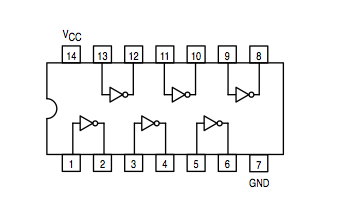
Inverter: 74LS04 | |
|
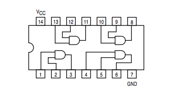
AND gate: 74LS08 | |
|
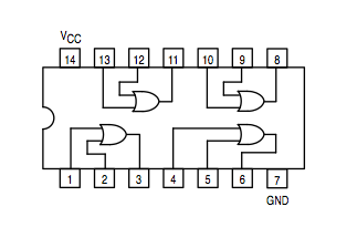
OR gate: 74LS32 | |
|
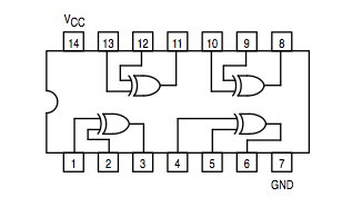
Exclusive OR: 74LS86 |
Breadboard, Digital Kit
Explanations will be given in class.
We will refer to the diagram below for wiring integrated circuits in the Logic Lab.
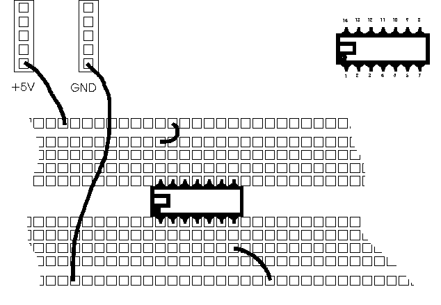
Figure 1:Wiring of an IC on the breadboard. Always identify pin 1 of the IC which is on the left (or below) the notch or circle embossed on the top of the chip
Data Sheets
If you need to refer to the data sheets of various chips during the lab, you can click on any of the links below:
74LS00
74LS01
74LS02
74LS03
74LS04
74LS05
74LS08
74LS09
74LS10
74LS12
74LS13
74LS15
74LS20
74LS21
74LS22
74LS26
74LS27
74LS28
74LS30
74LS32
74LS33
74LS37
74LS38
74LS40
74LS42
74LS47
74LS48
74LS51
74LS54
74LS55
74LS74
74LS75
74LS76
74LS83
74LS85
74LS86
74LS90
74LS9
74LS13
74HCT24
74LS24
74HCT24
74LS25
74HCT54.
