Difference between revisions of "CSC270 Lab 4 2011"
(→Experiment #3 (A view of things to come...)) |
(→Experiment #3 (A view of things to come...)) |
||
| (2 intermediate revisions by the same user not shown) | |||
| Line 35: | Line 35: | ||
=Experiment #3 (A view of things to come...)= | =Experiment #3 (A view of things to come...)= | ||
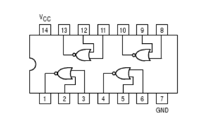
| − | Wire up the following circuit that uses NOR gates (be careful, NORs do not have the same pinout as the other gates). | + | Wire up the following circuit that uses NOR gates (be careful, NORs do not have the same pinout as the other gates, as shown below). |
Connect the two inputs (on the left) to switches, and the outputs (on the right) to LEDs. | Connect the two inputs (on the left) to switches, and the outputs (on the right) to LEDs. | ||
| Line 43: | Line 43: | ||
This is a very unusual circuit. Play with the inputs a bit and figure out its behavior... | This is a very unusual circuit. Play with the inputs a bit and figure out its behavior... | ||
| + | <br /> | ||
<br /> | <br /> | ||
| + | <br /> | ||
| + | <center>[[Image:74LS02.png|300px]]</center> | ||
<br /> | <br /> | ||
Latest revision as of 11:04, 14 February 2011
--D. Thiebaut 10:42, 14 February 2011 (EST)
Contents
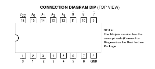
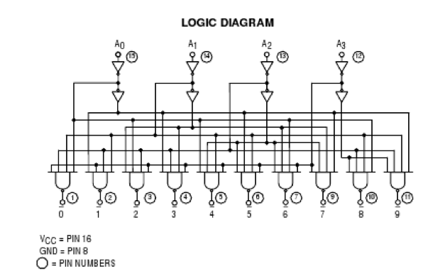
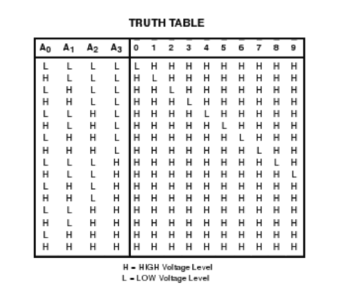
The 74LS42 Datasheet
Experiment #1
Use a 74LS42 to implement a 3-to-8 decoder with enable and active-low outputs. The challenge here is that you only have 4 LEDs to show outputs. You cannot use one LED connected to two different outputs, or one of the outputs will get damaged in the process. You'll have to switch back and forth between LEDs and signals to show one set of outputs, for example the lower 4 output bits, and the other set of outputs, i.e. the upper 4 output bits.
Experiment #2
Use a 74LS42 to implement a majority voter of 3 input signals.
You can only use one extra chip, in addition to the 74LS42!
Experiment #3 (A view of things to come...)
Wire up the following circuit that uses NOR gates (be careful, NORs do not have the same pinout as the other gates, as shown below). Connect the two inputs (on the left) to switches, and the outputs (on the right) to LEDs.
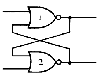
This is a very unusual circuit. Play with the inputs a bit and figure out its behavior...
