Difference between revisions of "Tutorial: Introduction to the Arduino"
(→Control Statements) |
|||
| (74 intermediate revisions by the same user not shown) | |||
| Line 1: | Line 1: | ||
--[[User:Thiebaut|D. Thiebaut]] 15:18, 20 April 2011 (EDT) | --[[User:Thiebaut|D. Thiebaut]] 15:18, 20 April 2011 (EDT) | ||
---- | ---- | ||
| + | <div style="text-align:right;"> | ||
| + | <google1 style="2"></google1> | ||
| + | </div> | ||
| + | |||
__TOC__ | __TOC__ | ||
<br /> | <br /> | ||
| Line 7: | Line 11: | ||
|- | |- | ||
| | | | ||
| − | == | + | ==Before You Start Playing...== |
|} | |} | ||
| + | |||
| + | ===Video Introduction=== | ||
| + | * Excellent introduction to the Arduino, its team, and some of the projects. | ||
| + | <br /> | ||
| + | <br /> | ||
| + | <center> | ||
| + | <videoflash type="vimeo">18539129</videoflash> | ||
| + | </center> | ||
| + | <br /> | ||
| + | <br /> | ||
===Good Reference Pages=== | ===Good Reference Pages=== | ||
* [http://arduino.cc/en/Reference/HomePage The Arduino Language Reference] | * [http://arduino.cc/en/Reference/HomePage The Arduino Language Reference] | ||
* [http://arduino.cc/en/Guide/Windows The ''Getting Started'' guide] | * [http://arduino.cc/en/Guide/Windows The ''Getting Started'' guide] | ||
| − | + | * [http://cs.smith.edu/classwiki/index.php/CSC231_Page The CSC231] Arduino project page (Fall 2008) | |
===Good Tutorials on the Web=== | ===Good Tutorials on the Web=== | ||
| − | * [http://dma.ucla.edu/senselab/node/350 Arduino Tutorial at UCLA] | + | * [http://dma.ucla.edu/senselab/node/350 Arduino Tutorial at UCLA] (''currently unavailable'') |
| − | |||
===Notes for Mac Users=== | ===Notes for Mac Users=== | ||
* You may have to install special drivers for your Mac to see the Arduino through the USB Port. Look here for more info: http://www.ftdichip.com/Drivers/VCP.htm | * You may have to install special drivers for your Mac to see the Arduino through the USB Port. Look here for more info: http://www.ftdichip.com/Drivers/VCP.htm | ||
| + | |||
| + | <br /> | ||
| + | <br /> | ||
{| style="width:100%; background:goldenrod" | {| style="width:100%; background:goldenrod" | ||
|- | |- | ||
| | | | ||
| − | == | + | |
| + | ==Important Concepts to Understand before Starting...== | ||
|} | |} | ||
| Line 33: | Line 50: | ||
<center>[[Image:CSC270_ArduinoSetupLaptop.png|400px]]</center> | <center>[[Image:CSC270_ArduinoSetupLaptop.png|400px]]</center> | ||
<br /> | <br /> | ||
| − | + | {| border="1" | |
| + | ! Action | ||
| + | ! Laptop | ||
| + | ! Arduino | ||
| + | |- | ||
| + | | | ||
* Programs are written on the laptop | * Programs are written on the laptop | ||
| + | | align="center" | X | ||
| + | | align="center" | | ||
| + | |- | ||
| + | | | ||
* Programs are compiled on the laptop | * Programs are compiled on the laptop | ||
| + | | align="center" | X | ||
| + | | align="center" | | ||
| + | |- | ||
| + | | | ||
* Programs are downloaded to the Arduino | * Programs are downloaded to the Arduino | ||
| + | | align="center" | src | ||
| + | | align="center" | dest | ||
| + | |- | ||
| + | | | ||
* Programs run on the Arduino | * Programs run on the Arduino | ||
| − | * Programs output information via the USB cable, and this information is captured by the IDE which shows it in the Serial Monitor. | + | | align="center" | |
| − | * The Arduino inputs information that the User types in the Serial Monitor. This information is sent via the USB cable to the Arduino. | + | | align="center" | X |
| + | |- | ||
| + | | | ||
| + | * Programs output text information via the USB cable, and this information is captured by the IDE which shows it in the Serial Monitor. | ||
| + | | align="center" | display | ||
| + | | align="center" | print | ||
| + | |- | ||
| + | | | ||
| + | * The Arduino inputs character information that the User types in the Serial Monitor. This information is sent via the USB cable to the Arduino. | ||
| + | | align="center" | char sent in Monitor | ||
| + | | align="center" | get 1 char from USB | ||
| + | |} | ||
| + | <br /> | ||
| + | |||
| + | <!-- ============================================================== --> | ||
| + | <!-- ============================================================== --> | ||
| + | <!-- ============================================================== --> | ||
| + | {| style="width:100%; background:goldenrod" | ||
| + | |- | ||
| + | | | ||
| + | |||
| + | ==Circuits and Systems == | ||
| + | |} | ||
| + | <br /> | ||
| + | * This is just a very rough introduction to the Arduino circuits, and useful only as a support for an in-class presentation of the Arduino. Please refer to http://arduino.cc/en/Tutorial/Foundations for in-depth coverage of all these concepts. | ||
| + | <br /> | ||
| + | <center>[[Image:DiecimilaSpecs.png]]</center> | ||
| + | <br /> | ||
<br /> | <br /> | ||
| + | {| style="width:100%; background:whitesmoke" | ||
| + | |- | ||
| + | | | ||
| + | ===Digital I/Os=== | ||
| + | |} | ||
| + | <br /> | ||
| + | * Main reference: http://arduino.cc/en/Tutorial/DigitalPins | ||
| + | * 14 pins | ||
| + | * Each can be '''input''' or '''output''' | ||
| + | * 5-Volt range | ||
| + | * 40 mA max | ||
| + | * Internal pull-up resistor (disconnected by default) | ||
| + | * Special pins | ||
| + | ** Pins 0 & 1: Used to exchange data with USB | ||
| + | ** Pins 2 & 3: can be used as interrupt pins (i.e. can trigger '''events''') | ||
| + | ** Pins 3, 5, 6, 9, 10, and 11: 8-bit Pulse-Width Modulation. | ||
| + | ** Pin 13: on-board LED. | ||
| + | <br /> | ||
| + | <br /> | ||
| + | {| style="width:100%; background:whitesmoke" | ||
| + | |- | ||
| + | | | ||
| + | |||
| + | ===Analog Input=== | ||
| + | |} | ||
| + | <br /> | ||
| + | * 6 Analog inputs | ||
| + | * each 10-bit resolution | ||
| + | * range = 0 - 5 Volts. | ||
| + | ** 0V --> 0 | ||
| + | ** 5V --> 1023 | ||
| + | * '''Important Note''': Analog input pins can also be used as digital output pins. See http://www.arduino.cc/en/Tutorial/AnalogInputPins for more information. | ||
| + | |||
| + | <br /> | ||
| + | <br /> | ||
| + | |||
| + | {| style="width:100%; background:whitesmoke" | ||
| + | |- | ||
| + | | | ||
| + | |||
| + | ===Simulated Analog Output (PWM)=== | ||
| + | |} | ||
| + | <br /> | ||
| + | * Digital Pins 3, 5, 6, 9, 10, and 11 can be used in 8-bit Pulse-Width Modulation. | ||
| + | * Frequency = 500Hz, ==> Period = 2 ms | ||
| + | * 8-bit value: range = 0 --> 255 | ||
| + | ** 0 --> 0% duty cycle: constant low level output | ||
| + | ** 127 --> 50% duty cycle: 50% of the time, the signal is low, 50% high. | ||
| + | ** 255 --> 100% duty cycle: constant high level output | ||
| + | *taken from http://www.arduino.cc/en/Tutorial/PWM | ||
| + | <br /> | ||
| + | <br /> | ||
| + | <center>[[Image:ArduinoPWM.png]]</center> | ||
| + | <br /> | ||
| + | <!-- ============================================================== --> | ||
| + | <!-- ============================================================== --> | ||
| + | <!-- ============================================================== --> | ||
{| style="width:100%; background:goldenrod" | {| style="width:100%; background:goldenrod" | ||
|- | |- | ||
| Line 49: | Line 167: | ||
|} | |} | ||
| + | {| style="width:100%; background:whitesmoke" | ||
| + | |- | ||
| + | | | ||
===Comments=== | ===Comments=== | ||
| + | |} | ||
| Line 59: | Line 181: | ||
well */ | well */ | ||
| + | {| style="width:100%; background:whitesmoke" | ||
| + | |- | ||
| + | | | ||
===Setup() and Loop()=== | ===Setup() and Loop()=== | ||
| − | + | |} | |
| + | <br /> | ||
* [http://arduino.cc/en/Reference/Setup Setup()] | * [http://arduino.cc/en/Reference/Setup Setup()] | ||
* [http://arduino.cc/en/Reference/Loop Loop()] | * [http://arduino.cc/en/Reference/Loop Loop()] | ||
| − | ===Output=== | + | <br /> |
| + | <br /> | ||
| + | {| style="width:100%; background:whitesmoke" | ||
| + | |- | ||
| + | | | ||
| + | |||
| + | ===Text Input/Output=== | ||
| + | |} | ||
====Output strings from the Arduino to Laptop==== | ====Output strings from the Arduino to Laptop==== | ||
| Line 128: | Line 261: | ||
<br /> | <br /> | ||
| − | ====Statements === | + | {| style="width:100%; background:whitesmoke" |
| + | |- | ||
| + | | | ||
| + | |||
| + | ===Statements=== | ||
| + | |} | ||
statement; | statement; | ||
| Line 140: | Line 278: | ||
} | } | ||
| − | ====Control Statements=== | + | {| style="width:100%; background:whitesmoke" |
| + | |- | ||
| + | | | ||
| + | ===Control Statements=== | ||
| + | |} | ||
| − | + | ====IF==== | |
if ( ''condition equal to 0 or different from 0'' ) { | if ( ''condition equal to 0 or different from 0'' ) { | ||
| Line 153: | Line 295: | ||
| − | + | ====FOR==== | |
* same syntax and structure as in Java. | * same syntax and structure as in Java. | ||
| Line 165: | Line 307: | ||
| − | + | ====SWITCH==== | |
* works with ''countable'' variables (not floats). | * works with ''countable'' variables (not floats). | ||
| Line 181: | Line 323: | ||
} | } | ||
| − | + | ====WHILE==== | |
| + | |||
| − | while (expression evaluating to 0 or something different from 0 ) { | + | '''while''' (expression evaluating to 0 or something different from 0 ) { |
statement; | statement; | ||
statement; | statement; | ||
| Line 190: | Line 333: | ||
| − | + | ====BREAK/CONTINUE==== | |
| + | |||
* '''break''': break out of the most inner loop it is located in. | * '''break''': break out of the most inner loop it is located in. | ||
| Line 196: | Line 340: | ||
| − | ====Variables and Data Types=== | + | |
| + | {| style="width:100%; background:whitesmoke" | ||
| + | |- | ||
| + | | | ||
| + | ===Variables and Data Types=== | ||
| + | |} | ||
* void | * void | ||
| − | * boolean | + | * '''boolean''' |
| − | * char | + | * '''char''' |
* unsigned char | * unsigned char | ||
* byte | * byte | ||
| − | * int | + | * '''int''' |
* unsigned int | * unsigned int | ||
* word | * word | ||
* long | * long | ||
* unsigned long | * unsigned long | ||
| − | * float | + | * '''float''' |
* double | * double | ||
* string ''(array of chars)'' | * string ''(array of chars)'' | ||
| − | * String ''(object)'' | + | * '''String''' ''(object)'' (see http://arduino.cc/en/Reference/StringObject) |
| − | * array | + | * array (see http://arduino.cc/en/Reference/Array) |
| + | |||
| + | ::'''Examples''' | ||
| + | int LEDpin = 5; // LED on pin 5 | ||
| + | int switchPin = 13; // momentary switch on 13, other side connected to ground | ||
| + | boolean running = false; | ||
| + | |||
| + | char myChar = 'A'; | ||
| + | char myChar = 65; // both are equivalent | ||
| + | |||
| + | byte b = B10010; // "B" is the binary formatter (B10010 = 18 decimal) | ||
| + | |||
| + | float myfloat; | ||
| + | float sensorCalbrate = 1.117; | ||
| + | |||
| + | char Str1[15]; | ||
| + | char Str2[8] = {'a', 'r', 'd', 'u', 'i', 'n', 'o'}; | ||
| + | char Str3[8] = {'a', 'r', 'd', 'u', 'i', 'n', 'o', '\0'}; | ||
| + | char Str4[ ] = "arduino"; | ||
| + | char Str5[8] = "arduino"; | ||
| + | char Str6[15] = "arduino"; | ||
| + | |||
| + | String stringOne = "Hello String"; // using a constant String | ||
| + | String stringOne = String('a'); // converting a constant char into a String | ||
| + | String stringTwo = String("This is a string"); // converting a constant string into a String object | ||
| + | String stringOne = String(stringTwo + " with more"); // concatenating two strings | ||
| + | String stringOne = String(13); // using a constant integer | ||
| + | String stringOne = String(analogRead(0), DEC); // using an int and a base | ||
| + | String stringOne = String(45, HEX); // using an int and a base (hexadecimal) | ||
| + | String stringOne = String(255, BIN); // using an int and a base (binary) | ||
| + | String stringOne = String(millis(), DEC); // using a long and a base | ||
| + | |||
| + | int myInts[6]; | ||
| + | int myPins[] = {2, 4, 8, 3, 6}; | ||
| + | int mySensVals[6] = {2, 4, -8, 3, 2}; | ||
| + | char message[6] = "hello"; | ||
| + | <tanbox> | ||
| + | ;Exercise | ||
| + | : Create a sketch based on the Blink sketch (in File/Examples/1. Basics) that outputs alternatively "hello" one second, then your name the next second, in an endless loop. | ||
| + | </tanbox> | ||
| + | <br /> | ||
| + | <tanbox> | ||
| + | ;Exercise | ||
| + | : Create a sketch that outputs the word '''Green''' one second, then outputs '''Yellow''' the next, then outputs '''Red''' the next, returning to '''Green''' the second after that. See example below. | ||
| + | </tanbox> | ||
| + | <br /> | ||
| + | <tanbox> | ||
| + | ;Exercise | ||
| + | : Same as previous one, but make the delay between outputs a quarter of a second. | ||
| + | </tanbox> | ||
| + | |||
| + | <br /> | ||
| + | <br /> | ||
| + | <center>[[Image:CSC270_Arduino_GreenYellowRed.png|500px]]</center> | ||
| + | <br /> | ||
| + | <br /> | ||
| + | {| style="width:100%; background:whitesmoke" | ||
| + | |- | ||
| + | | | ||
| + | ===Functions=== | ||
| + | |} | ||
| + | * Taken from http://arduino.cc/en/Reference/FunctionDeclaration | ||
| + | |||
| + | <br /> | ||
| + | <center>[[Image:ArduinoAnatomyOfACFunction.png]]</center> | ||
| + | |||
| + | <br /> | ||
| + | <br /> | ||
| + | * '''Static''' variables | ||
| + | |||
| + | int process( int offset ) { | ||
| + | '''static''' int current=0; | ||
| + | |||
| + | current += offset; | ||
| + | ... | ||
| + | } | ||
| + | |||
| + | <!-- ============================================================== --> | ||
| + | <!-- ============================================================== --> | ||
| + | <!-- ============================================================== --> | ||
| + | {| style="width:100%; background:goldenrod" | ||
| + | |- | ||
| + | | | ||
| + | |||
| + | ==Digital Output== | ||
| + | |} | ||
| + | |||
| + | {| style="width:100%; background:whitesmoke" | ||
| + | |- | ||
| + | | | ||
| + | ===The Basics=== | ||
| + | |} | ||
| + | * The Arduino sports 14 output pins: Digital 0 to 13 | ||
| + | * Steps: | ||
| + | ** in '''setup()''', use '''pinMode()''' to identify what pin you will use, and set the direction of data transfer as OUTPUT | ||
| + | ** in '''loop()''', use '''digitalWrite( )''' to output HIGH or LOW to that pin. | ||
| + | |||
| + | * Example | ||
| + | |||
| + | <code><pre> | ||
| + | int ledPin = 13; // LED connected to digital pin 13 | ||
| + | |||
| + | void setup() | ||
| + | { | ||
| + | pinMode(ledPin, OUTPUT); // sets the digital pin as output | ||
| + | } | ||
| + | |||
| + | void loop() | ||
| + | { | ||
| + | digitalWrite(ledPin, HIGH); // sets the LED on | ||
| + | delay(1000); // waits for a second | ||
| + | digitalWrite(ledPin, LOW); // sets the LED off | ||
| + | delay(1000); // waits for a second | ||
| + | } | ||
| + | </pre></code> | ||
| + | |||
| + | |||
| + | {| style="width:100%; background:whitesmoke" | ||
| + | |- | ||
| + | | | ||
| + | ===Exercises=== | ||
| + | |} | ||
| + | |||
| + | <tanbox> | ||
| + | ;Exercise | ||
| + | :Follow the steps from http://arduino.cc/en/Tutorial/Blink and create a similar system. Instead of soldering the LED to the resistor, use the breadboard or aligator clips. | ||
| + | </tanbox> | ||
| + | |||
| + | <br /> | ||
| + | <center>[[Image:LED_Diagram.png|300px]]</center> | ||
| + | <br /> | ||
| + | <br /> | ||
<tanbox> | <tanbox> | ||
;Exercise | ;Exercise | ||
| − | : | + | :Use the same approach and create a sketch that will controls 3 LEDs (which will represent a Green light, Yellow light, and Red light), and will alternate between all three in a cycle. |
| + | </tanbox> | ||
| + | |||
| + | <br /> | ||
| + | <center>[[Image:CSC270_Arduino_1_LED.png|300px]]</center> | ||
| + | <br /> | ||
| + | <br /> | ||
| + | <br /> | ||
| + | <br /> | ||
| + | |||
| + | <br /> | ||
| + | {| style="width:100%; background:goldenrod" | ||
| + | |- | ||
| + | | | ||
| + | |||
| + | ==Digital Input== | ||
| + | |} | ||
| + | |||
| + | * The approach is similar to the one take for output bits. | ||
| + | |||
| + | <code><pre> | ||
| + | |||
| + | void setup() { | ||
| + | Serial.begin(9600); | ||
| + | pinMode(2, INPUT); | ||
| + | } | ||
| + | |||
| + | void loop() { | ||
| + | int sensorValue = digitalRead(2); | ||
| + | Serial.println(sensorValue, DEC); | ||
| + | } | ||
| + | |||
| + | </pre></code> | ||
| + | |||
| + | {| style="width:100%; background:whitesmoke" | ||
| + | |- | ||
| + | | | ||
| + | ===Exercises=== | ||
| + | |} | ||
| + | |||
| + | |||
| + | <tanbox> | ||
| + | ;Exercise | ||
| + | :Follow the steps from http://arduino.cc/en/Tutorial/Button, and control the on-board LED with the external switch. | ||
| + | </tanbox> | ||
| + | <br /> | ||
| + | <br /> | ||
| + | <tanbox> | ||
| + | ;Exercise: | ||
| + | :Replace the on-board LED by an external LED wired in a way similiar to the previous exercise. | ||
| + | </tanbox> | ||
| + | |||
| + | <br /> | ||
| + | <center>[[Image:CSC270_Arduino_1_Button.png|600px]] | ||
| + | </center> | ||
| + | |||
| + | <br /> | ||
| + | {| style="width:100%; background:goldenrod" | ||
| + | |- | ||
| + | | | ||
| + | ==Analog Input== | ||
| + | |} | ||
| + | |||
| + | * Use the '''analogRead()''' function to read an analog value from a given pin: | ||
| + | |||
| + | void loop() { | ||
| + | int sensorValue = '''analogRead(A0)'''; // Note: A0 is predefined | ||
| + | Serial.println(sensorValue, DEC); // display value on Monitor | ||
| + | } | ||
| + | |||
| + | <br /> | ||
| + | {| style="width:100%; background:whitesmoke" | ||
| + | |- | ||
| + | | | ||
| + | ===Exercise=== | ||
| + | |} | ||
| + | |||
| + | <br /> | ||
| + | <tanbox> | ||
| + | ;Exercise | ||
| + | :Follow the steps presented in http://arduino.cc/en/Tutorial/AnalogReadSerial and build a simple meter that measures the rotation of a potentiometer. | ||
</tanbox> | </tanbox> | ||
| + | <br /> | ||
| + | <center>[[Image:ArduinoAnalogReadWithPot.png]]</center> | ||
| + | <br /> | ||
| + | <br /> | ||
| + | {| style="width:100%; background:goldenrod" | ||
| + | |- | ||
| + | | | ||
| + | |||
| + | ==Projects== | ||
| + | |} | ||
| + | |||
| + | |||
| + | <bluebox> | ||
| + | ;Project 1 | ||
| + | :Create a frequency measuring tool that will display the frequency of a square-wave signal such as the one generated by the HP Test Boards. | ||
| + | </bluebox> | ||
| + | <br /> | ||
| + | <br /> | ||
| + | |||
| + | <center>[[Image:TextronixScopeFace1.jpg|200px]]</center> | ||
| + | |||
| + | <br /> | ||
| + | <br /> | ||
| + | <bluebox> | ||
| + | ;Project 2 | ||
| + | : Build a simple project around the FYM-12881AURUG-11 8x8 LED Matrix. | ||
| + | </bluebox> | ||
| + | * See Yang Li's [http://cs.smith.edu/classwiki/index.php/231a-ac_Final_Presentation CSC231 Final Project] page for additional information on how to wire up the LED Matrix, and/or how to program it. | ||
| + | |||
| + | <br /> | ||
| + | <center> | ||
| + | [[Image:8by8LEDMatrix.jpg]] | ||
| + | [[Image:YangLi8by8LEDMatrixArduinoWiring.jpg|300px]] | ||
<br /> | <br /> | ||
| − | <br /><br /><br /><br /><br /><br /><br /><br /><br /><br /> | + | [[Image:LedMatrixSchematics.jpg|450px]] |
| + | <br /> | ||
| + | </center> | ||
| + | <br /> | ||
| + | <br /> | ||
| + | ===Some Ideas=== | ||
| + | <center> | ||
| + | [[Image:8by8LEDMatrix1.jpg|200px]] | ||
| + | [[Image:8by8LEDMatrix2.jpg|200px]] | ||
| + | [[Image:8by8LEDMatrix3.jpg|200px]] | ||
| + | [[Image:8by8LEDMatrix4.jpg|200px]] | ||
| + | [[Image:8by8LEDMatrix5.jpg|200px]] | ||
| + | [[Image:8by8LEDMatrix6.jpg|200px]] | ||
| + | [[Image:8by8LEDMatrix7.jpg|200px]] | ||
| + | [[Image:8by8LEDMatrix8.jpg|200px]] | ||
| + | <videoflash>BUniwJWElLQ</videoflash> | ||
| + | <videoflash>GmTBR-BWYj8</videoflash> | ||
| + | </center> | ||
| + | |||
| + | <br /><br /><br /><br /><br /><br /><br /><br /> | ||
[[Category:CSC270]][[Category:Arduino]][[Category:Labs]] | [[Category:CSC270]][[Category:Arduino]][[Category:Labs]] | ||
Latest revision as of 08:04, 21 June 2011
--D. Thiebaut 15:18, 20 April 2011 (EDT)
Contents
Before You Start Playing... |
Video Introduction
- Excellent introduction to the Arduino, its team, and some of the projects.
Good Reference Pages
- The Arduino Language Reference
- The Getting Started guide
- The CSC231 Arduino project page (Fall 2008)
Good Tutorials on the Web
- Arduino Tutorial at UCLA (currently unavailable)
Notes for Mac Users
- You may have to install special drivers for your Mac to see the Arduino through the USB Port. Look here for more info: http://www.ftdichip.com/Drivers/VCP.htm
Important Concepts to Understand before Starting... |
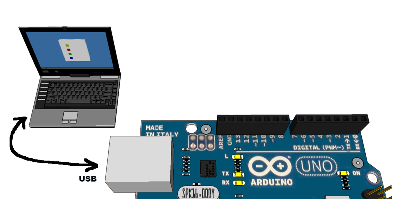
| Action | Laptop | Arduino |
|---|---|---|
|
X | |
|
X | |
|
src | dest |
|
X | |
|
display | |
|
char sent in Monitor | get 1 char from USB |
Circuits and Systems |
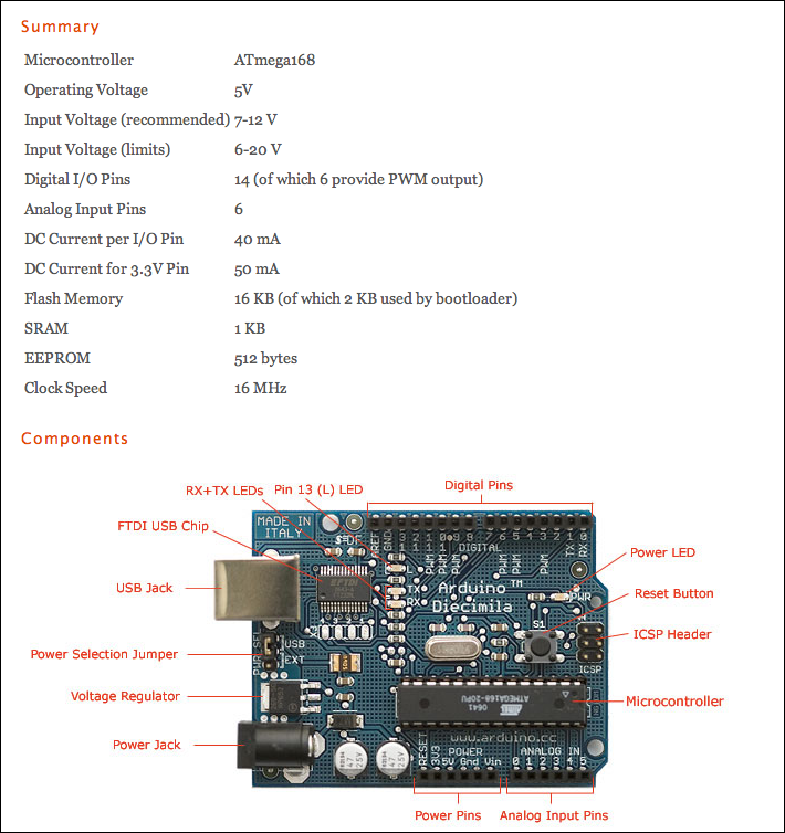
- This is just a very rough introduction to the Arduino circuits, and useful only as a support for an in-class presentation of the Arduino. Please refer to http://arduino.cc/en/Tutorial/Foundations for in-depth coverage of all these concepts.
Digital I/Os |
- Main reference: http://arduino.cc/en/Tutorial/DigitalPins
- 14 pins
- Each can be input or output
- 5-Volt range
- 40 mA max
- Internal pull-up resistor (disconnected by default)
- Special pins
- Pins 0 & 1: Used to exchange data with USB
- Pins 2 & 3: can be used as interrupt pins (i.e. can trigger events)
- Pins 3, 5, 6, 9, 10, and 11: 8-bit Pulse-Width Modulation.
- Pin 13: on-board LED.
Analog Input |
- 6 Analog inputs
- each 10-bit resolution
- range = 0 - 5 Volts.
- 0V --> 0
- 5V --> 1023
- Important Note: Analog input pins can also be used as digital output pins. See http://www.arduino.cc/en/Tutorial/AnalogInputPins for more information.
Simulated Analog Output (PWM) |
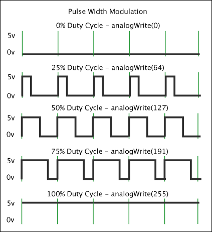
- Digital Pins 3, 5, 6, 9, 10, and 11 can be used in 8-bit Pulse-Width Modulation.
- Frequency = 500Hz, ==> Period = 2 ms
- 8-bit value: range = 0 --> 255
- 0 --> 0% duty cycle: constant low level output
- 127 --> 50% duty cycle: 50% of the time, the signal is low, 50% high.
- 255 --> 100% duty cycle: constant high level output
- taken from http://www.arduino.cc/en/Tutorial/PWM
An Introduction to C in the Arduino Context |
Comments |
// this is a comment
/* and so is this */
/* and
    this
    as
    well */
Setup() and Loop() |
Text Input/Output |
Output strings from the Arduino to Laptop
- Done with the Serial library
- Use Serial.begin() to set the baud rate (# of bits per second)
- Then output strings with Serial.println( ... ) or Serial.print( ... )
void setup() {
 Serial.begin( 38400 );
 Serial.println( "Hello there!" );
}

void loop() {
 delay(1000);              // wait for a second
 Serial.println( "hello again!" );
}
Output numbers
- Taken from http://arduino.cc/en/Serial/Print
- Serial.print(78) gives "78"
- Serial.print(1.23456) gives "1.23"
- Serial.print(byte(78)) gives "N" (whose ASCII value is 78)
- Serial.print('N') gives "N"
- Serial.print("Hello world.") gives "Hello world."
- An optional second parameter specifies the base (format) to use; permitted values are BYTE, BIN (binary, or base 2), OCT (octal, or base 8), DEC (decimal, or base 10), HEX (hexadecimal, or base 16). For floating point numbers, this parameter specifies the number of decimal places to use. For example:
- Serial.print(78, BYTE) gives "N"
- Serial.print(78, BIN) gives "1001110"
- Serial.print(78, OCT) gives "116"
- Serial.print(78, DEC) gives "78"
- Serial.print(78, HEX) gives "4E"
- Serial.println(1.23456, 0) gives "1"
- Serial.println(1.23456, 2) gives "1.23"
- Serial.println(1.23456, 4) gives "1.2346"
Inputting characters
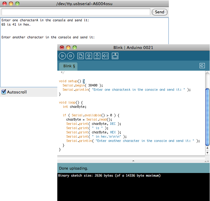
- Use Serial.read() and Serial.available(), as illustrated below
void setup() {
  Serial.begin( 38400 );
  Serial.println( "Enter one characterA in the console and send it: " );
}

void loop() {
  int charByte;

  if ( Serial.available() > 0 ) {
    charByte = Serial.read();
    Serial.print( charByte, DEC );
    Serial.print( " is " );
    Serial.print( charByte, HEX );
    Serial.print( " in hex.\n\n\n" );
    Serial.println( "Enter another character in the console and send it: " );
  }
}
Statements |
statement;
statement;
statement;
// comment
statement;
compound-statement {
       statement;
       statement;
}
Control Statements |
IF
if ( condition equal to 0 or different from 0 ) {
      // Action A
}
else {
      // Action B
}
FOR
- same syntax and structure as in Java.
- you can declare the variable in the loop.
- the variable is undefined outside the loop.
for ( int i = 0; i < 100; i++ ) {
      statement;
      statement;
}
SWITCH
- works with countable variables (not floats).
switch (var) {
   case 1:
     //do something when var equals 1
     break;
   case 2:
     //do something when var equals 2
     break;
   default:
     // if nothing else matches, do the default
     // default is optional
 }
WHILE
while (expression evaluating to 0 or something different from 0 ) {
    statement;
    statement;
    statement;
}
BREAK/CONTINUE
- break: break out of the most inner loop it is located in.
- continue: skips the remainder of the current loop and returns to the closest for or while statement.
Variables and Data Types |
- void
- boolean
- char
- unsigned char
- byte
- int
- unsigned int
- word
- long
- unsigned long
- float
- double
- string (array of chars)
- String (object) (see http://arduino.cc/en/Reference/StringObject)
- array (see http://arduino.cc/en/Reference/Array)
- Examples
int LEDpin = 5;       // LED on pin 5
int switchPin = 13;   // momentary switch on 13, other side connected to ground
boolean running = false;

char myChar = 'A';
char myChar = 65;      // both are equivalent

byte b = B10010;  // "B" is the binary formatter (B10010 = 18 decimal)

float myfloat;
float sensorCalbrate = 1.117;

char Str1[15];
char Str2[8] = {'a', 'r', 'd', 'u', 'i', 'n', 'o'};
char Str3[8] = {'a', 'r', 'd', 'u', 'i', 'n', 'o', '\0'};
char Str4[ ] = "arduino";
char Str5[8] = "arduino";
char Str6[15] = "arduino";

String stringOne = "Hello String";                     // using a constant String
String stringOne =  String('a');                       // converting a constant char into a String
String stringTwo =  String("This is a string");        // converting a constant string into a String object
String stringOne =  String(stringTwo + " with more");  // concatenating two strings
String stringOne =  String(13);                        // using a constant integer
String stringOne =  String(analogRead(0), DEC);        // using an int and a base
String stringOne =  String(45, HEX);                   // using an int and a base (hexadecimal)
String stringOne =  String(255, BIN);                  // using an int and a base (binary)
String stringOne =  String(millis(), DEC);             // using a long and a base

int myInts[6];
int myPins[] = {2, 4, 8, 3, 6};
int mySensVals[6] = {2, 4, -8, 3, 2};
char message[6] = "hello";
- Exercise
- Create a sketch based on the Blink sketch (in File/Examples/1. Basics) that outputs alternatively "hello" one second, then your name the next second, in an endless loop.
- Exercise
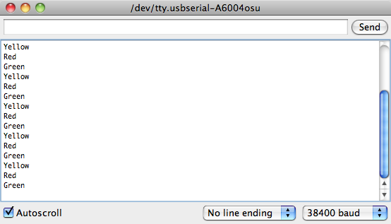
- Create a sketch that outputs the word Green one second, then outputs Yellow the next, then outputs Red the next, returning to Green the second after that. See example below.
- Exercise
- Same as previous one, but make the delay between outputs a quarter of a second.
Functions |
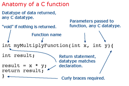
- Static variables
 int process( int offset ) {
      static int current=0;

      current += offset;
      ...
 }
Digital Output |
The Basics |
- The Arduino sports 14 output pins: Digital 0 to 13
- Steps:
- in setup(), use pinMode() to identify what pin you will use, and set the direction of data transfer as OUTPUT
- in loop(), use digitalWrite( ) to output HIGH or LOW to that pin.
- Example
int ledPin = 13;                 // LED connected to digital pin 13

void setup()
{
  pinMode(ledPin, OUTPUT);      // sets the digital pin as output
}

void loop()
{
  digitalWrite(ledPin, HIGH);   // sets the LED on
  delay(1000);                  // waits for a second
  digitalWrite(ledPin, LOW);    // sets the LED off
  delay(1000);                  // waits for a second
}
Exercises |
- Exercise
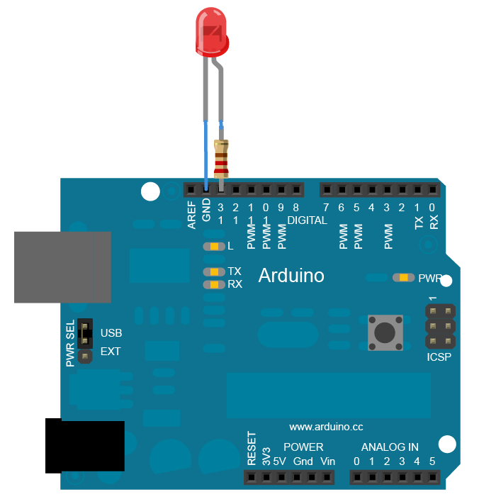
- Follow the steps from http://arduino.cc/en/Tutorial/Blink and create a similar system. Instead of soldering the LED to the resistor, use the breadboard or aligator clips.
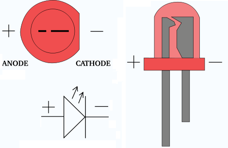
- Exercise
- Use the same approach and create a sketch that will controls 3 LEDs (which will represent a Green light, Yellow light, and Red light), and will alternate between all three in a cycle.
Digital Input |
- The approach is similar to the one take for output bits.
void setup() {
  Serial.begin(9600);
  pinMode(2, INPUT);
}

void loop() {
  int sensorValue = digitalRead(2);
  Serial.println(sensorValue, DEC);
}
Exercises |
- Exercise
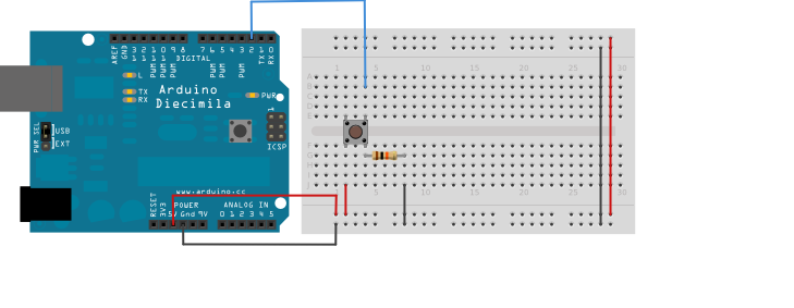
- Follow the steps from http://arduino.cc/en/Tutorial/Button, and control the on-board LED with the external switch.
- Exercise
- Replace the on-board LED by an external LED wired in a way similiar to the previous exercise.
Analog Input |
- Use the analogRead() function to read an analog value from a given pin:
void loop() {
  int sensorValue = analogRead(A0);  // Note: A0 is predefined
  Serial.println(sensorValue, DEC);   // display value on Monitor
}
Exercise |
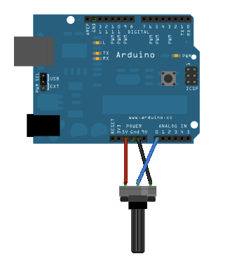
- Exercise
- Follow the steps presented in http://arduino.cc/en/Tutorial/AnalogReadSerial and build a simple meter that measures the rotation of a potentiometer.
Projects |
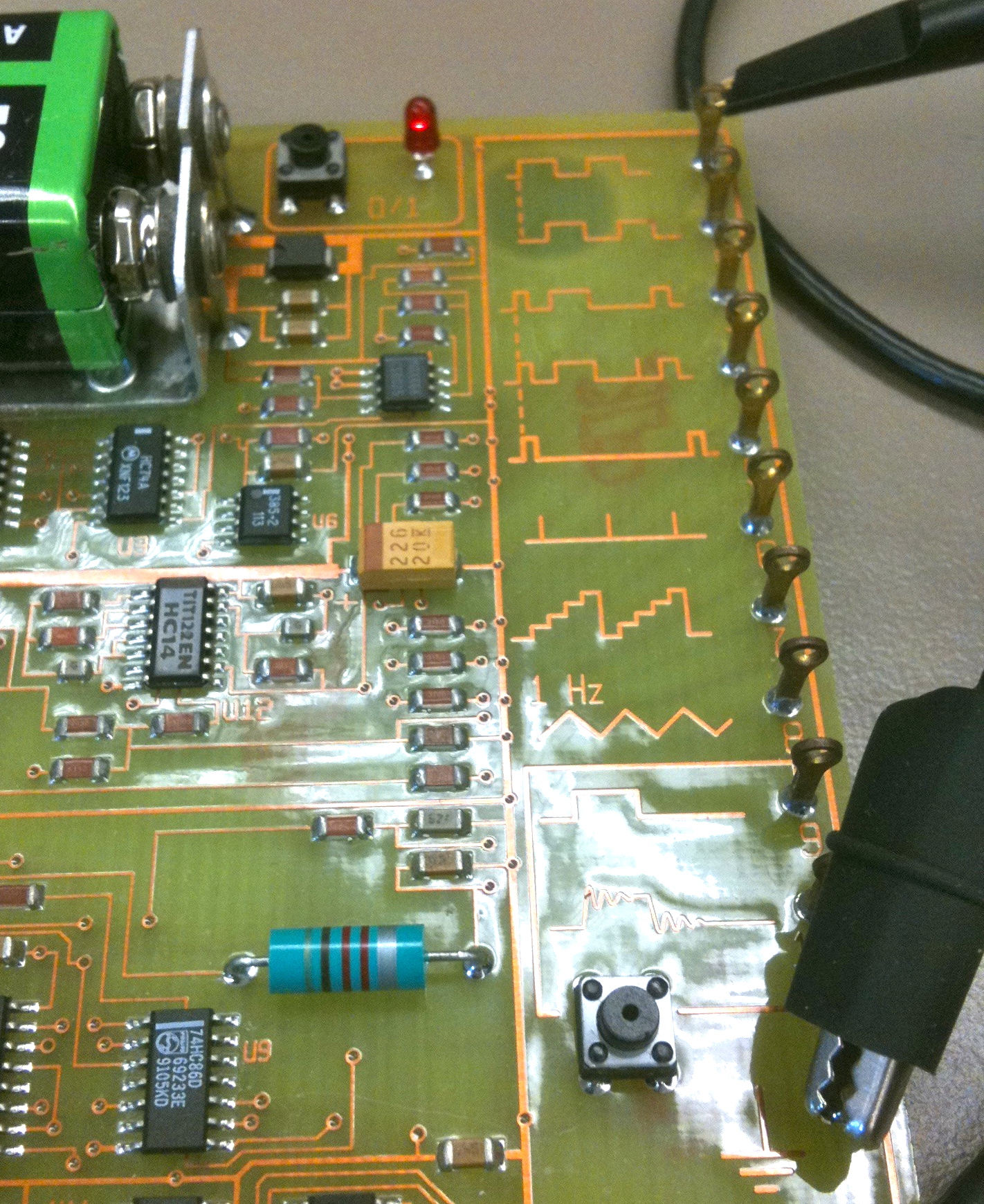
- Project 1
- Create a frequency measuring tool that will display the frequency of a square-wave signal such as the one generated by the HP Test Boards.
- Project 2
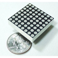
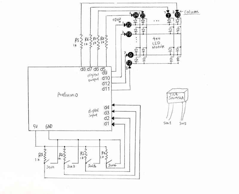
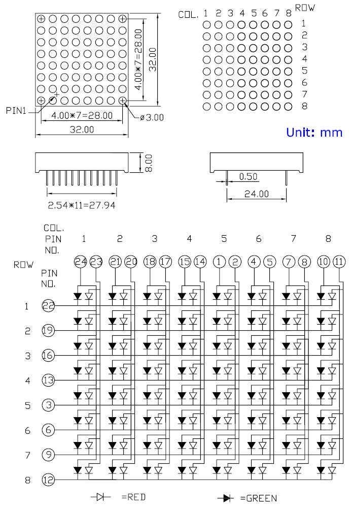
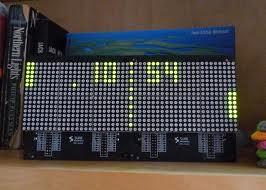
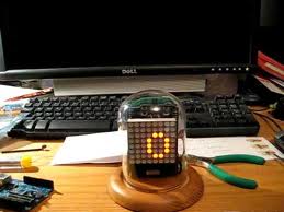
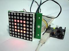
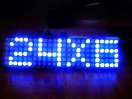
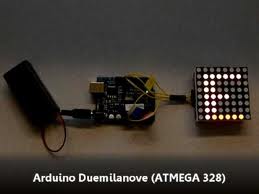
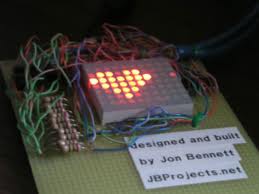
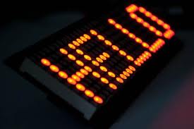
- Build a simple project around the FYM-12881AURUG-11 8x8 LED Matrix.
- See Yang Li's CSC231 Final Project page for additional information on how to wire up the LED Matrix, and/or how to program it.
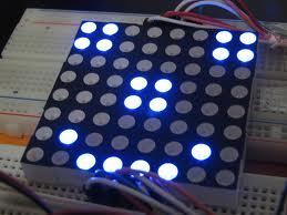
Some Ideas
