Difference between revisions of "CSC103 Logic Lab 2014"
(→The NOT gate) |
(→The NOT gate) |
||
| (2 intermediate revisions by the same user not shown) | |||
| Line 62: | Line 62: | ||
# You can now turn ON the breadboard by clicking on the ''traffic light'' icon. If you skip this steps, clicking on the switch to activate it will result in adding more wires to the board! | # You can now turn ON the breadboard by clicking on the ''traffic light'' icon. If you skip this steps, clicking on the switch to activate it will result in adding more wires to the board! | ||
# Click on the switch to send 1s (switch is <font color="red">red</font>) or 0s (<font color="dark grey">grey</font>) to the inverter, and verify that the LED always shows the opposite color of the switch. This should fully verify the inverter's truth table: | # Click on the switch to send 1s (switch is <font color="red">red</font>) or 0s (<font color="dark grey">grey</font>) to the inverter, and verify that the LED always shows the opposite color of the switch. This should fully verify the inverter's truth table: | ||
| − | + | <br /> | |
| − | + | <br /> | |
| − | |||
<center> | <center> | ||
{| border="1" cellpadding="10" cellspacing="0" | {| border="1" cellpadding="10" cellspacing="0" | ||
| Line 78: | Line 77: | ||
|} | |} | ||
</center> | </center> | ||
| − | + | ||
<br /> | <br /> | ||
<br /> | <br /> | ||
Latest revision as of 20:40, 24 August 2014
--D. Thiebaut (talk) 13:15, 24 August 2014 (EDT)
Contents
The Simple Logic Simulator (SLS)
Buttons
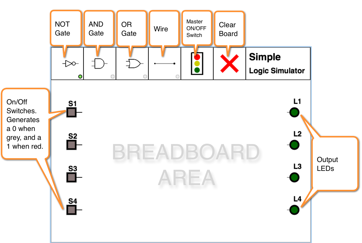
THe Simple Logic Simulator is a Javascript simulator written with the Google WebKit library, by D. Thiebaut. It allows for the logic design of simple logic circuits using inverters, AND gates, and OR gates. It sports 4 inputs switches and 4 output LEDs.
- The switches
- The switches are used to generate binary signals with the value 0 or 1. When the switch is grey (OFF), it generates a 0, and when red (ON), it generates a 1. A switch can be connected to multiple inputs.
- Inverter Gates
- Click on the Inverter Gate button to position inverters on the breadboard area. A green marker at the bottom right of the Inverter Gate button indicates when this mode is active. In this mode, clicking anywhere on the breadboard area will add another inverter.
- AND Gates
- Click on the AND Gate button to position AND gates on the breadboard area. As for the Inverter Gate button, the small red marker at the bottom right of the button indicates if this mode is in effect.
- OR Gates
- Click on the OR Gate button to position one or several OR gates on the breadboard area.
- ON/OFF Master Switch.
- Click on this button to energize the circuit you have just wired up. When the light is green, any input combination generated by the 4 switches will be combined by the gates and sent to the LEDs. The green light turns off as soon as you click on one of the gate buttons, or on the CLEAR button (see below).
- CLEAR
- The big red cross is the clear button. Clicking on it will remove all the gates and wired you positioned on the breadboard. There is no undo button, so if you make a mistake, you'll have to clear the board and redo the wiring!
- Output LEDS
- The circular LEDs on the right will turn ON (green) when they receive a 1 signal, and grey when they receive a 0. Only one output can be connected to an LED at a given time.
Video Introduction
Watch the video to get a sense of how it operates.
NOT, AND, and OR gates
The NOT gate
The purpose of this section is to put a NOT gate (inverter) on the breadboard, connect it to a switch
and an LED and verify its truth table. This will replicate the first set of steps illustrated in
the video you just watched.
- Make sure you have opened the simulator (available here).
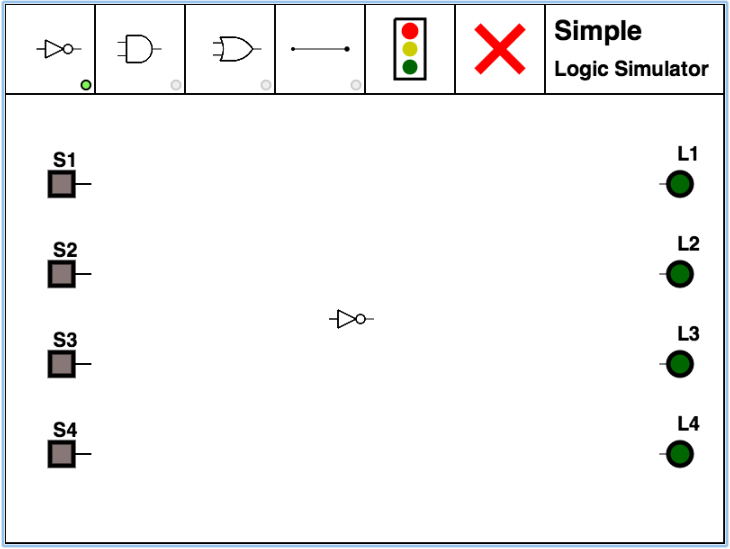
- Click on the NOT gate, in the top left corner.
- Click in the middle of the breadboard.
- You should see an inverter appear where you clicked.
- Click on the wire button, 4th from the top left. Its little round marker should turn green.
- When adding wires, you must always click first an output, and second an input. In other words always go in the sense of the way information travels, from left to right.
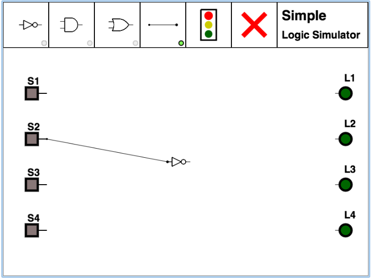
- Pick on of the 4 switches on the leff and click on its output (tiny line coming out of it).
- A small blinking cross will appear, indicating that you have connected one end of the wire.
- Now click on the input of the inverter, i.e. the small line sticking out on the left side of the gate.
- If everything went well, you should now have a wire connecting the switch to the inverter, as illustrated below
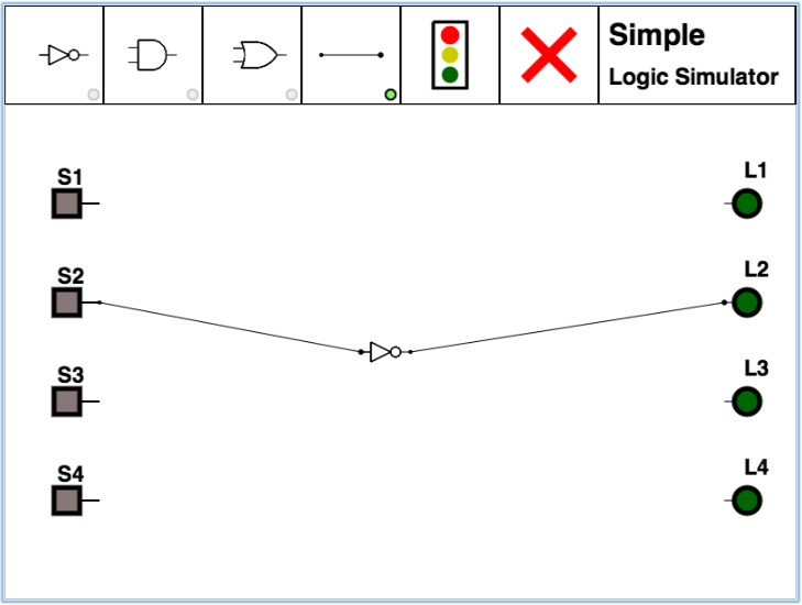
- Similarly, connect the output of the inverter to one of the LEDs on the right-hand side. Make sure you start from the output of the inverter and end with the input of the LED. Remember, always go left to right.
- You should have a wire between the inverter and the LED, as illustrated below.
- You can now turn ON the breadboard by clicking on the traffic light icon. If you skip this steps, clicking on the switch to activate it will result in adding more wires to the board!
- Click on the switch to send 1s (switch is red) or 0s (grey) to the inverter, and verify that the LED always shows the opposite color of the switch. This should fully verify the inverter's truth table:
| input | output = not input |
| 0 | 1 |
| 1 | 0 |
The OR Gate
You can now clear the breadboard by clicking on the big red cross in the top menu.
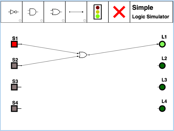
Take the similar steps as you did for the NOT gate, and wire up an OR gate with 2 inputs. Try all possible combinations of the two inputs and verify that you can test all possible combinations present in the truth table for OR:
| input1 | input2 | input1 OR input2 |
| 0 | 0 | 0 |
| 0 | 1 | 1 |
| 1 | 0 | 1 |
| 1 | 1 | 1 |
The AND Gate
Take the similar steps as you did for the OR gate, and wire up an AND gate with 2 inputs. Try all possible combinations of the two inputs and verify that its truth table is the following one:
| input1 | input2 | input1 OR input2 |
| 0 | 0 | 0 |
| 0 | 1 | 0 |
| 1 | 0 | 0 |
| 1 | 1 | 1 |
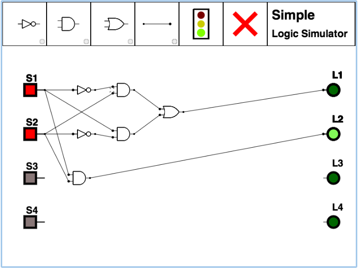
A 2-Bit Adder
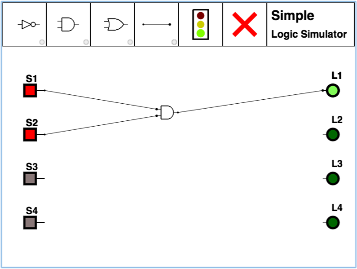
Wire up the circuit of the binary adder which we have seen in class.
Try all possible combinations of the inputs, and verify that the outputs correspond to the sum of the two inputs, in binary.
| bit1 | + | bit2 | = | carry | sum | |
|---|---|---|---|---|---|---|
| 0 | + | 0 | = | 0 | 0 | |
| 0 | + | 1 | = | 0 | 1 | |
| 1 | + | 0 | = | 0 | 1 | |
| 1 | + | 1 | = | 1 | 0 |
