Difference between revisions of "Tutorial: Arduino and XBee Communication"
(→Setup) |
(→Software) |
||
| (One intermediate revision by the same user not shown) | |||
| Line 57: | Line 57: | ||
* To test normal operation, open the '''Blink''' program from the examples (available via the '''File''' menu): | * To test normal operation, open the '''Blink''' program from the examples (available via the '''File''' menu): | ||
| − | <source lang="C"> | + | ::<source lang="C"> |
/* | /* | ||
Blink | Blink | ||
| Line 130: | Line 130: | ||
* Created Arduino program in IDE: | * Created Arduino program in IDE: | ||
| − | <source lang="C"> | + | ::<source lang="C"> |
/* | /* | ||
Xbee1 | Xbee1 | ||
Latest revision as of 07:40, 30 April 2015
--D. Thiebaut 17:47, 9 April 2012 (EDT)
This page shows how to quickly test the connection and good operating conditions of two XBee modules.
Contents
Setup
The setup is simple:
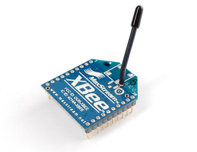
- Windows PC <---USB-cable---> Xbee (receiver) <--wireless--> XBee (Xmitter) <---> Arduino
- Instead of a pure Windows machine, we're using a MacPro running Windows in Parallels. This is our Windows machine.
- Windows is connected to an XBee via a USB cable.
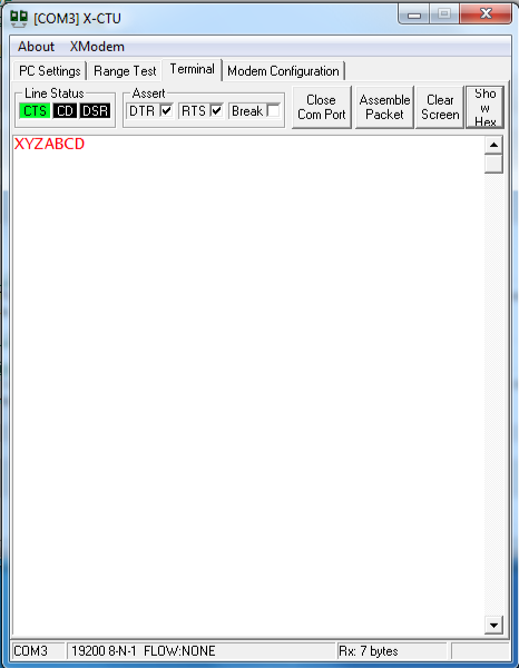
- Windows runs the X-CTU software that interacts with the XBee. This XBee is in receiving mode.
- An Arduino is connected to the MacPro. The Arduino is connected via 4 wires to another XBee module. This XBee module works in transmit mode.
- The Arduino sends a character of the alphabet to the XBee every second. First 'A', then 'B', all the way to 'Z', then 'A' again, ad infinitum.
Testing XBees on the Windows PC
- Note: The 2 XBee modules are purchased from ADAFruit.com
- Testing steps:
- Downloaded X-CTU software from ladyada.net
- X-CTU upgraded itself once started
- Followed the directions from the configure page at ladyada.net
- Module #1:(marked with "1" in silver marker on square near antenna)
 Communication with modem. OK
 Modem type = XB24
 Modem firmware version = 10EC

 Serial Number = 13A2004078E552
- Following steps from the configure page, reset the baud rate to 19200, and upgraded to most recent firmware.
- Module #2:(marked with "2" in silver marker on square near antenna)
 Communication with modem. OK
 Modem type = XB24
 Modem firmware version = 10EC

 Serial Number = 13A2004078E642
- Following steps from the configure page, reset the baud rate to 19200, and upgraded Module 2 to most recent firmware.
Testing Arduino
- Install Arduino IDE on 2nd computer (a MacPro)
- Launch Arduino app IDE
- Connect Arduino board to MacPro via USB cable.
- Use the Tools menu to set the model to Diecimila and the USB port to the appropriate port.
- To test normal operation, open the Blink program from the examples (available via the File menu):
/*
  Blink
  Turns on an LED on for one second, then off for one second, repeatedly.

  This example code is in the public domain.
 */

void setup() {
  // initialize the digital pin as an output.
  // Pin 13 has an LED connected on most Arduino boards:
  pinMode(13, OUTPUT);
}

void loop() {
  digitalWrite(13, HIGH);   // set the LED on
  delay(1000);              // wait for a second
  digitalWrite(13, LOW);    // set the LED off
  delay(1000);              // wait for a second
}
- Upload to Arduino
- Verify that the LED blinks.
Connection of Arduino to XBee
Hardware
- Very simple connections from Arduino to XBee with 4 wires:
| Arduino | <---> | XBee |
|---|---|---|
|
+5V |
<---> |
+5V |
|
GND |
<---> |
GND |
|
Digital Pin 2 |
<---> |
TxD |
|
Digital Pin 3 |
<---> |
RxD |
Software
- Use the Arduino SoftwareSerial page on the SoftwareSerial library. Great reference for figuring out how Arduino can talk to XBee via a serial port.
- Created Arduino program in IDE:
/*
  Xbee1
  D. Thiebaut

  Makes Arduino send 1 character via XBee wireless to another XBee connected
  to a computer via a USB cable.

  The circuit:
  * RX is digital pin 2 (connect to TX of XBee)
  * TX is digital pin 3 (connect to RX of XBee)

  Based on a sketch created back in the mists of time by Tom Igoe
  itself based on Mikal Hart's example

*/

#include <SoftwareSerial.h>

SoftwareSerial xbee(2, 3); // RX, TX
char c = 'A';
int  pingPong = 1;

void setup()  {
   Serial.begin(57600);
   Serial.println( "Arduino started sending bytes via XBee" );

   // set the data rate for the SoftwareSerial port
   xbee.begin( 19200 );
}

void loop()  {
  // send character via XBee to other XBee connected to Mac
  // via USB cable
  xbee.print( c );

  //--- display the character just sent on console ---
  Serial.println( c );

  //--- get the next letter in the alphabet, and reset to ---
  //--- 'A' once we have reached 'Z'.
  c = c + 1;
  if ( c>'Z' )
       c = 'A';

  //--- switch LED on Arduino board every character sent---
  if ( pingPong == 0 )
    digitalWrite(13, LOW);
  else
    digitalWrite(13, HIGH);
  pingPong = 1 - pingPong;
  delay( 1000 );
}
- Compiled program.
- Uploaded program to Arduino.
- In Windows use X-CTU software and click on Terminal Tab to monitor data received wirelessly from Arduino.

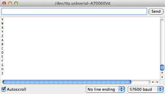
- On Arduino side, in IDE, uses Tools menu and opened the console window to see Arduino print characters as they are sent:

It works!
- Observe video. Notice the characters of the alphabet appearing once a second in both windows. One is the console, attached to the transmitting Arduino, the other one is the Terminal window of the X-CTU software on the Windows side, receiving the characters sent wirelessly.
Communication with a Mac running OSX
If you want to connect the receiving XBee to a Mac instead of a Windows PC, use Ashley Hughes solution, and read the characters sent by the XBee on the Mac Terminal.
- Connect the XBee via the USB cable to the Mac
- Open the Terminal application
- Enter the following command:
ls /dev/tty.*
- and note the different USB devices listed (of the form /dev/tty.usbserial-######).
- Pick one of the devices and try this:
screen /dev/tty.usbserial-##### 19200
- If you're lucky, you'll start seeing characters of the alphabet appear on the screen of the Terminal window, one a second, going through the whole alphabet.
- For more information on how to use the screen command to established a serial connection to a USB device, check out this page.
