Difference between revisions of "CSC103 Final Exam 2017"
(→Problem 1: Logic Design (33%)) |
|||
| (5 intermediate revisions by the same user not shown) | |||
| Line 12: | Line 12: | ||
| − | + | ||
=Problem 1: Logic Design (33%)= | =Problem 1: Logic Design (33%)= | ||
| + | <br /> | ||
| + | In logic design, a ''majority voter'' is a circuit that has 3 boolean inputs, and outputs the value that appears on 2 or more of the inputs. For example, if two of the inputs are 1 (or true), then the output is 1 (or true). If two of the inputs are 0 (or false), then the output is 0 (or false). Of course, if all three inputs are 1, then the output is 1. If all inputs are 0, the output is 0. | ||
<br /> | <br /> | ||
The following three logic circuits are candidates for a majority voter. | The following three logic circuits are candidates for a majority voter. | ||
<br /> | <br /> | ||
| − | [[Image:CSC103FinalCircuit1.png| | + | Circuit A: |
| + | [[Image:CSC103FinalCircuit1.png|400px|center]] | ||
<br /> | <br /> | ||
<br /> | <br /> | ||
| − | [[Image:CSC103FinalCircuit2.png| | + | Circuit B: |
| + | [[Image:CSC103FinalCircuit2.png|400px|center]] | ||
<br /> | <br /> | ||
<br /> | <br /> | ||
| − | [[Image:CSC103FinalCircuit3.png| | + | Circuit C: |
| + | [[Image:CSC103FinalCircuit3.png|400px|center]] | ||
<br /> | <br /> | ||
<br /> | <br /> | ||
| − | |||
Which circuit or circuits are majority voters? | Which circuit or circuits are majority voters? | ||
| − | + | <br /> | |
* Circuit A? | * Circuit A? | ||
* Circuit B? | * Circuit B? | ||
| Line 36: | Line 40: | ||
* Circuits A and C? | * Circuits A and C? | ||
* Circuits B and C? | * Circuits B and C? | ||
| − | * | + | * All three? |
| − | + | * None of them? | |
| − | + | <br /> | |
| + | <font color="magenta">(Added 10/24/17 10:00 a.m.)Note that if a circuit outputs the correct answer in most combinations of inputs, but outputs the '''wrong''' answer for one combination, then it is '''not''' a majority voter. A true majority voter would '''always''' output the correct answer given any combination of inputs.</font> | ||
| + | <br /> | ||
| + | Please provide your answer in the '''Problem 1''' Section of the Final Exam on Moodle. | ||
<br /> | <br /> | ||
| − | |||
<br /> | <br /> | ||
| + | |||
=Problem 2: Assembly (33%)= | =Problem 2: Assembly (33%)= | ||
<br /> | <br /> | ||
| Line 83: | Line 90: | ||
[[File:CSC103ProcessingFinal2017.png|200px|center]] | [[File:CSC103ProcessingFinal2017.png|200px|center]] | ||
<br /> | <br /> | ||
| − | + | ||
<br /> | <br /> | ||
<br /> | <br /> | ||
| Line 89: | Line 96: | ||
<onlydft> | <onlydft> | ||
=Solutions= | =Solutions= | ||
| + | <br /> | ||
| + | ==Problem 1== | ||
| + | |||
| + | * Circuit B | ||
| + | <br /> | ||
| + | ==Problem 2== | ||
| + | <br /> | ||
| + | ;Question 1: | ||
| + | :It demonstrates that all computers are built using the von Neumann architecture, where both data and code reside in memory, and the program illustrates an example where code stores data over itself, changing its behavior. | ||
| + | |||
| + | ;Question 2: | ||
| + | :It computes the sum of 1 + 2 + 4 + 8 + 16, and stores this value in Memory Location 23. | ||
| + | |||
| + | ;Question 3: | ||
| + | :True | ||
| + | |||
| + | ;Question 4: | ||
| + | :False | ||
| + | |||
| + | ;Question 5: | ||
| + | :Grace Hopper -- computer bug | ||
| + | :von Neuman -- computer organization | ||
| + | :Claude Shannon -- doing arithmetic using logic | ||
| + | :Gordon Moore -- exponential growth | ||
| + | :George Bool -- true & false | ||
<br /> | <br /> | ||
==Problem 3 == | ==Problem 3 == | ||
Latest revision as of 09:00, 24 October 2017
--D. Thiebaut (talk) 22:30, 16 October 2017 (EDT)
This exam is a take-home exam for CSC103, Fall 2017. The exam is open-books, open-notes, and open-Web. It is given under the rules of the Smith College Honor Code, and the work your turn in must reflect your individual work. You cannot discuss any of the details of this exam with anybody except your instructor (Dominique Thiebaut). If you have a question, please post it on Piazza.
You cannot work in pairs on this exam.
This exam is due on Moodle on 25 October 2017 at 11:55 p.m.
Contents
Problem 1: Logic Design (33%)
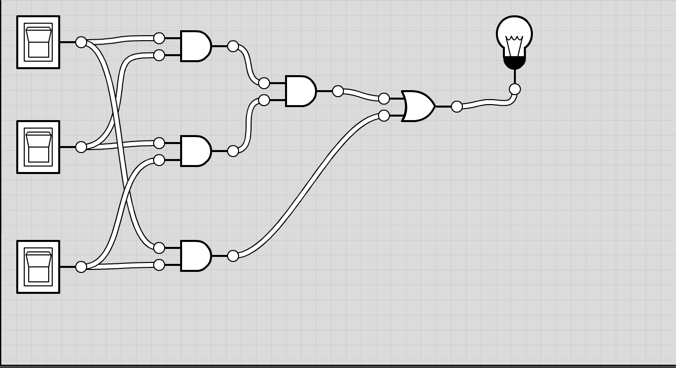
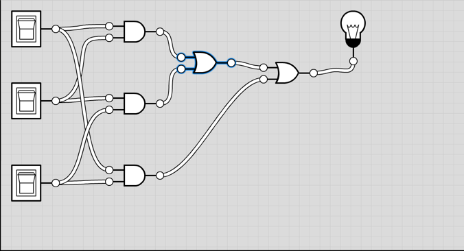
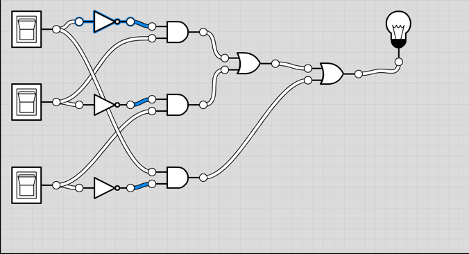
In logic design, a majority voter is a circuit that has 3 boolean inputs, and outputs the value that appears on 2 or more of the inputs. For example, if two of the inputs are 1 (or true), then the output is 1 (or true). If two of the inputs are 0 (or false), then the output is 0 (or false). Of course, if all three inputs are 1, then the output is 1. If all inputs are 0, the output is 0.
The following three logic circuits are candidates for a majority voter.
Circuit A:
Circuit B:
Circuit C:
Which circuit or circuits are majority voters?
- Circuit A?
- Circuit B?
- Circuit C?
- Circuits A and B?
- Circuits A and C?
- Circuits B and C?
- All three?
- None of them?
(Added 10/24/17 10:00 a.m.)Note that if a circuit outputs the correct answer in most combinations of inputs, but outputs the wrong answer for one combination, then it is not a majority voter. A true majority voter would always output the correct answer given any combination of inputs.
Please provide your answer in the Problem 1 Section of the Final Exam on Moodle.
Problem 2: Assembly (33%)
Answer the questions posted on Moodle, in the Problem 2 section.
Problem 3: Processing (33 %)
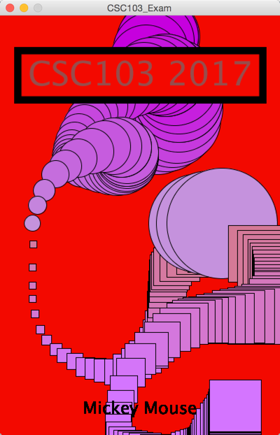
Write a Processing sketch that will emulate the original program I used to create the sketch demonstrated in movie, below.
- Include your name at the bottom of the display window (see the "Mickey Mouse" caption shown in the movie).
- The titled box at the top should show CSC103 2017 or another message of your choice, in a box with a wide stroke.
- The title box cannot be obliterated by circles or rectangles.
- The user must have the ability of drawing boxes or circles wherever she wants by pressing the mouse button.
- The squares and circles must change size as the mouse moves around (you decide on the size of your shapes).
- The squares and circles must change color as the mouse moves around (you decide what color to pick).
Additional Information
You may find the following functions useful for generating your graphic output:
- textAlign()
- stroke()
- textSize()
- strokeWeight()
- text()
Submission
- Submit two files on Moodle
- Save your sketch (File/Save As) under the name "CSC103Final" and locate the "CSC103Final.pde" file that Processing will have stored in a folder called CSC103Final on your laptop. You need to submit CSC103Final.pde to Moodle.
- Take a screenshot of your graphic window showing all the features, as illustrated below. Submit it on Moodle as well.
Each file counts for 1/2 of the grade for this problem.
<onlydft>
Solutions
Problem 1
- Circuit B
Problem 2
- Question 1
- It demonstrates that all computers are built using the von Neumann architecture, where both data and code reside in memory, and the program illustrates an example where code stores data over itself, changing its behavior.
- Question 2
- It computes the sum of 1 + 2 + 4 + 8 + 16, and stores this value in Memory Location 23.
- Question 3
- True
- Question 4
- False
- Question 5
- Grace Hopper -- computer bug
- von Neuman -- computer organization
- Claude Shannon -- doing arithmetic using logic
- Gordon Moore -- exponential growth
- George Bool -- true & false
Problem 3
// CSC103
// Final Exam
// Smith College
// Script creating a red window
// with the caption "CSC103 2017"
//
void setup() {
  // define the size of the window
  size( 400, 600 );
  smooth();

  // create red background
  background( 240, 19, 19 );
}

void draw() {
  strokeWeight( 1 );
  if ( mousePressed == true ) {
    if ( mouseY < 300 ) {
      fill( 196, mouseY/2, 219 );
      ellipse( mouseX, mouseY, mouseX/2, mouseX/2 );
    }
    else {
       fill( 211, 122, mouseY/2 );
       rect( mouseX, mouseY, mouseX/4, mouseX/4 );
    }
  }

  stroke( 0, 0, 0 );
  strokeWeight( 10 );
  fill(  240, 19, 19 );
  rect( 25, 50, 350, 70 );

  textAlign( CENTER );
  textSize( 48 );
  fill( 149, 77, 77 );
  text( "CSC103 2017", 200, 100 );

  textSize(24 );
  fill( 0, 0, 0 );
  text( "Mickey Mouse", width/2, height - 30 );
}


