Difference between revisions of "CSC270 Homework 9 2012"
(→Problem #1) |
(→Problem #2) |
||
| Line 19: | Line 19: | ||
=Problem #2= | =Problem #2= | ||
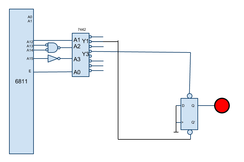
| − | Same question with the hardware shown below. | + | Same question with the hardware shown below. Y1' from the 7442 is connected to the CLR' input of the 7474. Y3' of the 7442 is connected to the PR' input of the 7474. Both the D and clock inputs of the 7474 are grounded. |
| + | |||
| + | Write the driver (2 functions) that can be used to turn the LED either ON, or OFF. | ||
<br /> | <br /> | ||
<center> | <center> | ||
Revision as of 14:45, 11 April 2012
--D. Thiebaut 15:31, 11 April 2012 (EDT)
This assignment is due on 4/18/12, at the beginning of the lab.
Problem #1
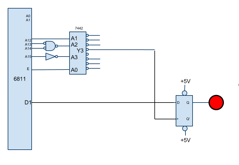
Write the driver for the hardware shown below, that consists of a 1-bit port attached to a red LED. The driver should be a collection of 2 functions, one to turn the LED ON, and another function to turn the LED OFF.
Note that who ever designed this circuit didn't use the same approach you took in the lab. In particular this design is more expensive in terms of gates. Also, make sure you notice that the port is connected to D1 of the Data Bus, and not D0 as you did in the lab...
Problem #2
Same question with the hardware shown below. Y1' from the 7442 is connected to the CLR' input of the 7474. Y3' of the 7442 is connected to the PR' input of the 7474. Both the D and clock inputs of the 7474 are grounded.
Write the driver (2 functions) that can be used to turn the LED either ON, or OFF.

