Difference between revisions of "Xilinx ISE Lab No. 1: Schematics Input"
(→Implementation Constraints File) |
|||
| Line 189: | Line 189: | ||
==Implementation Constraints File== | ==Implementation Constraints File== | ||
| − | The purpose of the ''Implementation Constraints File'' (ICF) is to associate ''input'' and ''output'' tabs with actual pins of the CPLD we | + | The purpose of the ''Implementation Constraints File'' (ICF) is to associate ''input'' and ''output'' tabs with actual pins of the CPLD chip we are using. |
| + | |||
| + | The image below shows all the pins available to us: | ||
| + | |||
| + | <br /> | ||
| + | <center>[[Image:CPLD_CoolRunnerII_PinOut.jpg|600px]]</center> | ||
| + | <br /> | ||
* Click on the '''Design''' tab of the left window. | * Click on the '''Design''' tab of the left window. | ||
| Line 200: | Line 206: | ||
* Select the ucf file and in the lower pane ('''processes''' pane), open the '''User Constraints''' option and click on '''Edit Constraints'''. | * Select the ucf file and in the lower pane ('''processes''' pane), open the '''User Constraints''' option and click on '''Edit Constraints'''. | ||
| − | |||
| − | |||
=References= | =References= | ||
<references /> | <references /> | ||
Revision as of 13:03, 16 April 2012
--D. Thiebaut 16:53, 14 April 2012 (EDT)
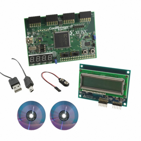
This lab is an introduction to Xilinx ISE and to the CoolRunner-II kit. Unfortunately the CoolRunner-II and its programming utility from Digilent works only with Windows XP, so we won't be able to download the design into the CPLD chip, but we can still energize and test the design with the ISE Simulator.
Note: You'll need a two-button mouse to work with the ISE. The Mac's magic mouse does not open up all the properties of the differen
Contents
Introduction
Xilinx's ISE is "Xilinx ISE[1] is a software tool produced by Xilinx for synthesis and analysis of HDL designs, which enables the developer to synthesize ("compile") their designs, perform timing analysis, examine RTL diagrams, simulate a design's reaction to different stimuli, and configure the target device with the programmer." [1]
The goal of this lab/tutorial is to get the reader familiar with the process of designing a simple digital electronic circuit, compiling it, and verifying it correct behavior with a simulator.
Knowledge of digital logic (basic gates, flip-flops, Moore machines) is assumed.
This lab is based on the excellent series of labs created for the CoolRunner CPLD by Tiffany Liu in her Independent Study in the CS. Dept. at Smith College.[2]
Installation of Xilinx ISE 13.4 on Windows 7
The first step is to install the ISE. It is a long process that can take more than an hour, so be prepared and start early!
If you have a Mac, you could use Parallels with Windows 7 running as a virtual machine. The ISE works in this setup as well.
The steps described below describe the installation of the most recent version of the ISE in April 2012: ISE 13.4
- Go to Xilinx's Download site
- Download ISE 13.4 full installer for windows
- When asked for a userId and password, you can either create your own Id or use this one:
-
This section is only visible to computers located at Smith College
-
- Click Next
- The file should start downloading. It takes about 30 minutes on a wireless connection.
- Unpack tar file into directory (in Dowloads folder). If Windows complain that it doesn't know how to unpack a file with a tar extension, download the 7-zip open-source utility, and use it to unpack the archive.
- Once in the exploded directory, run the xsetup application
- Pick WebPack when asked for what to install
- Accept all defaults and install in C:\Xilinx folder
Lab 1: Creating a 2-bit Adder with Schematics
New Project
- Open the ISE
- File/New Project
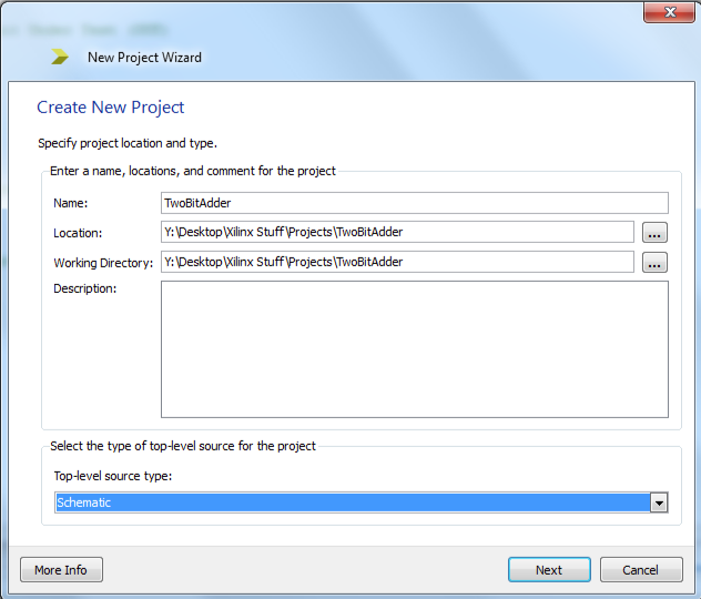
- Pick a name: TwoBitAdder
- Accept the default location
- Top-Level source: Schematics
- Next
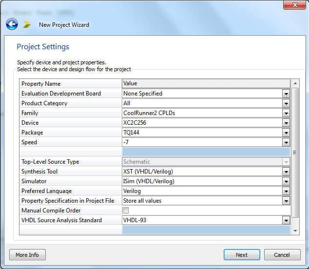
- Project Settings:
- Family: CoolRunner2 CPLDs
- Device: XC2C257 (this is the marking on the CPLD on the actual kit)
- Package: TQ144 (also marked on the CPLD on the actual kit)
- Speed: -7
- Keep all others unchanged.
New Source
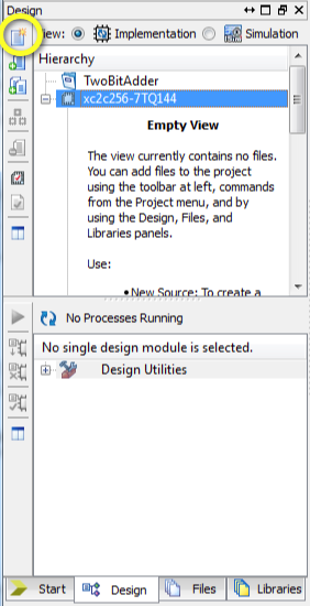
- Click on top left icon (see image to the right) to add a new source to the project.
- Pick Schematic as the type
- Name it with a name that makes sense, e.g. circuit1.
- If you need to remove gates, select the gate you want to delete, and click on the red cross icon in the top icon bar.
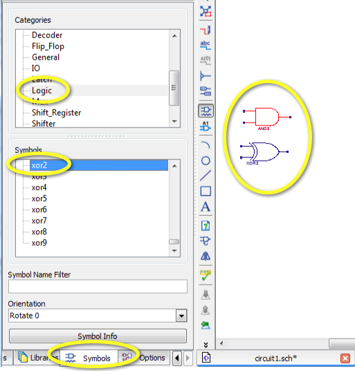
- Pick the Symbols tab (bottom of left pane)
- Select Logic in top list
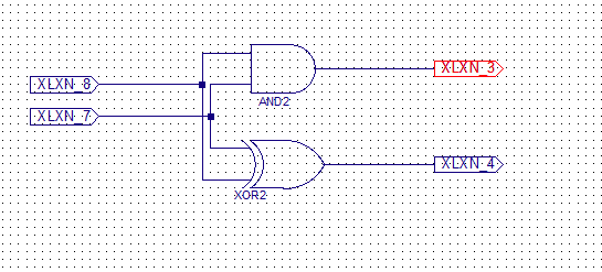
- Select And2 and Xor2 gates and position them on sreen
- Add wires between the inputs of the two gates (two vertical wires in the shape of [ brackets)
- Add two horizontal writes between the wires just inserted and points that will become input tags.
- Add two input tags to the two input wires just addes, and two output tags to the two outputs of the gates.
- Right-click on the Tabs and rename the two input ones as A and B, and the two output ones as Carry and Sum.
- Type Control-S to save the schematics to file.
Implementation Constraints File
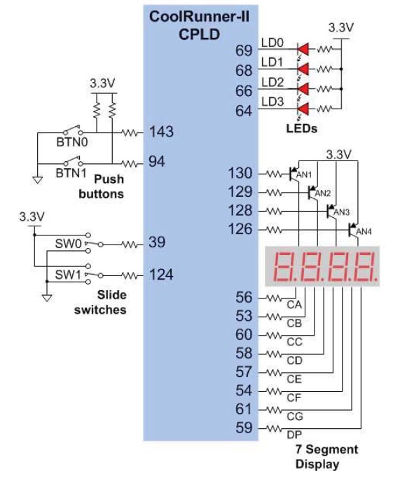
The purpose of the Implementation Constraints File (ICF) is to associate input and output tabs with actual pins of the CPLD chip we are using.
The image below shows all the pins available to us:
- Click on the Design tab of the left window.
- Select the circuit1.sch file and right click on it.
- New Source. Pick Implementation Constraints File. Name it something like circuits as well. (It will get its own extension.)
- Check under the circuit1.sch menu item, there should now be a file called circuit1.ucf.
- Select the ucf file and in the lower pane (processes pane), open the User Constraints option and click on Edit Constraints.
References
- ↑ Xilinx ISE, captured on wikipedia.org, April 2012.
- ↑ Tiffany Liu, CSC270 Labs on the CoolRunner-II, Independent Study, Fall 2011, cs.smith.edu/classwiki.
