Difference between revisions of "CSC103 Homework 2 2013"
(→Logic Simulator) |
(→Logic Simulator) |
||
| Line 44: | Line 44: | ||
! f | ! f | ||
|- | |- | ||
| − | | | + | | 0 |
| − | | | + | | 0 |
| − | | | + | | 0 |
| − | | | + | | 0 |
|- | |- | ||
| − | | | + | | 0 |
| − | | | + | | 0 |
| − | | | + | | 1 |
| − | | | + | | 0 |
|- | |- | ||
| − | | | + | | 0 |
| − | | | + | | 1 |
| − | | | + | | 0 |
| − | | | + | | 1 |
|- | |- | ||
| − | | | + | | 0 |
| − | | | + | | 1 |
| − | | | + | | 1 |
| − | | | + | | 0 |
|- | |- | ||
| − | | | + | | 1 |
| − | | | + | | 0 |
| − | | | + | | 0 |
| − | | | + | | 0 |
|- | |- | ||
| − | | | + | | 1 |
| − | | | + | | 0 |
| − | | | + | | 1 |
| − | | | + | | 1 |
|- | |- | ||
| − | | | + | | 1 |
| − | | | + | | 1 |
| − | | | + | | 0 |
| − | | | + | | 1 |
|- | |- | ||
| − | | | + | | 1 |
| − | | | + | | 1 |
| − | | | + | | 1 |
| − | | | + | | 0 |
|} | |} | ||
</center> | </center> | ||
Revision as of 06:48, 17 September 2013
--D. Thiebaut (talk) 07:41, 17 September 2013 (EDT)
This homework is due in class at 9:00 a.m. on 9/24/13. You can work on it in pairs, in which case you should put both names on the work you turn in. If you work in pairs, you must do the work together, i.e. meet one or several time to accomplish all the work with your partner. You need to turn in typed or handwritten work, on paper, on the due date. Make sure your homework is stapled, and that your name (and possibly that of your partner) is on all the sheets.
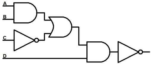
Logic Design Problem
- Question 1
- What is the truth table of this circuit? You can figure out the answer in several ways. One is to analyze the circuit "by hand" on a piece of paper and figure out the value of the different signals at the output of the different gates for all possible combinations of the inputs. The other one, longer but fool-proof, is to use the logic simulator we used in class, "wire-up" the circuit, and test its output for all combinations of the inputs.
- Question 2
- What is the boolean expression for the output of this circuit?
Logic Simulator
Assume that you have a boolean function f of three boolean variables a, b, and c.
The truth table of f is given below:
| a | b | c | f |
|---|---|---|---|
| 0 | 0 | 0 | 0 |
| 0 | 0 | 1 | 0 |
| 0 | 1 | 0 | 1 |
| 0 | 1 | 1 | 0 |
| 1 | 0 | 0 | 0 |
| 1 | 0 | 1 | 1 |
| 1 | 1 | 0 | 1 |
| 1 | 1 | 1 | 0 |
- Question 1
- What is the boolean expression for f, as a function of a, b, c, using the operators AND, OR and NOT?
- Question 2
- Draw on paper the circuit with AND, OR and NOT gates that implements the circuit for f
- Question 3
- Use the xLogic Simulator from this page ( or this one) and implement the circuit. Verify that it behaves correctly and follows the truth table of f. Take a screen capture of your simulator, print it, and attach it to your homework.
