Difference between revisions of "CSC270 Homework 2 2016"
(→Problem 3) |
(→Problem 3) |
||
| Line 29: | Line 29: | ||
* A ''majority voter'' is a circuit that has 3 inputs and one output. The output always represent the '''majority''' of the inputs. For example, when there are 2 or 3 1s on the inputs, then the output is 1. When there are 2 or 3 0s on the inputs, then the output is 0. | * A ''majority voter'' is a circuit that has 3 inputs and one output. The output always represent the '''majority''' of the inputs. For example, when there are 2 or 3 1s on the inputs, then the output is 1. When there are 2 or 3 0s on the inputs, then the output is 0. | ||
* Generate the truth table for the majority voter of 3 signals, a, b, and c. | * Generate the truth table for the majority voter of 3 signals, a, b, and c. | ||
| − | * Implement the majority voter with a 3-to-8 decoder, active-high outputs, and no enable signal and whatever other gates you need. | + | * Implement the majority voter with a 3-to-8 decoder, active-high outputs, and no enable signal and whatever other gates you need. Show the diagram (no need for pin numbers or part numbers). |
* Implement the majority voter with a 3-to-8 decoder, active-low outputs, active-low enable, and only NAND gates. | * Implement the majority voter with a 3-to-8 decoder, active-low outputs, active-low enable, and only NAND gates. | ||
<br /> | <br /> | ||
Revision as of 14:06, 4 February 2016
--D. Thiebaut (talk) 13:28, 4 February 2016 (EST)
This homework is due on 2/11/16 at 11:55 p.m. You can work individually or in a group of two.
Contents
Problem 1
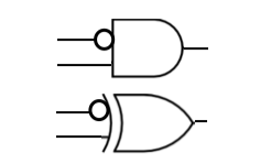
- The top gate, above, is an AND gate with an inverted input. The gate below it is an exclusive OR with an inverted input. The equation for the first one, assuming that the inputs are a and b, is a . (b'). The equation for the bottom one is a ⊕ b'
- Is one, or both of the gates above universal? Why or why not?
Problem 2
- Simplify the following functions using Karnaugh maps. Please show each Karnaugh map and its covers in your answer. If you can simplify the functions further by using some of the theorems of Table 2.2, then do so. Basically write the function so as to minimize the number of operators ( dot, plus, prime).
 f(a, b, c, d) = Σ (0, 1, 2, 3, 12, 13, 14, 15 )

 g(a, b, c, d) = Σ (0, 1, 2, 3, 4, 5, 6, 7, 8, 9, 10, 12, 13, 14, 15 )    # 11 missing!

 h(a, b, c) = Π ( 0, 1, 2, 3 )

 k(a, b, c) = Π (0, 1, 7, 8 )
Problem 3
- A majority voter is a circuit that has 3 inputs and one output. The output always represent the majority of the inputs. For example, when there are 2 or 3 1s on the inputs, then the output is 1. When there are 2 or 3 0s on the inputs, then the output is 0.
- Generate the truth table for the majority voter of 3 signals, a, b, and c.
- Implement the majority voter with a 3-to-8 decoder, active-high outputs, and no enable signal and whatever other gates you need. Show the diagram (no need for pin numbers or part numbers).
- Implement the majority voter with a 3-to-8 decoder, active-low outputs, active-low enable, and only NAND gates.
Problem 4
Write a python or java program that simulates a 3-to-8 decoder and an active-high enable, and active high outputs. You need to have a function that receives 4 inputs and returns 8 outputs. Make the program output the truth table for the decoder. Include both your source code, and the output of the program, clearly showing the truth table.
