Difference between revisions of "CSC270 Lab 3 2016"
(→Part 1: Ohm's Law) |
(→Measuring Voltages with the Agilent 34401A Voltmeter) |
||
| Line 20: | Line 20: | ||
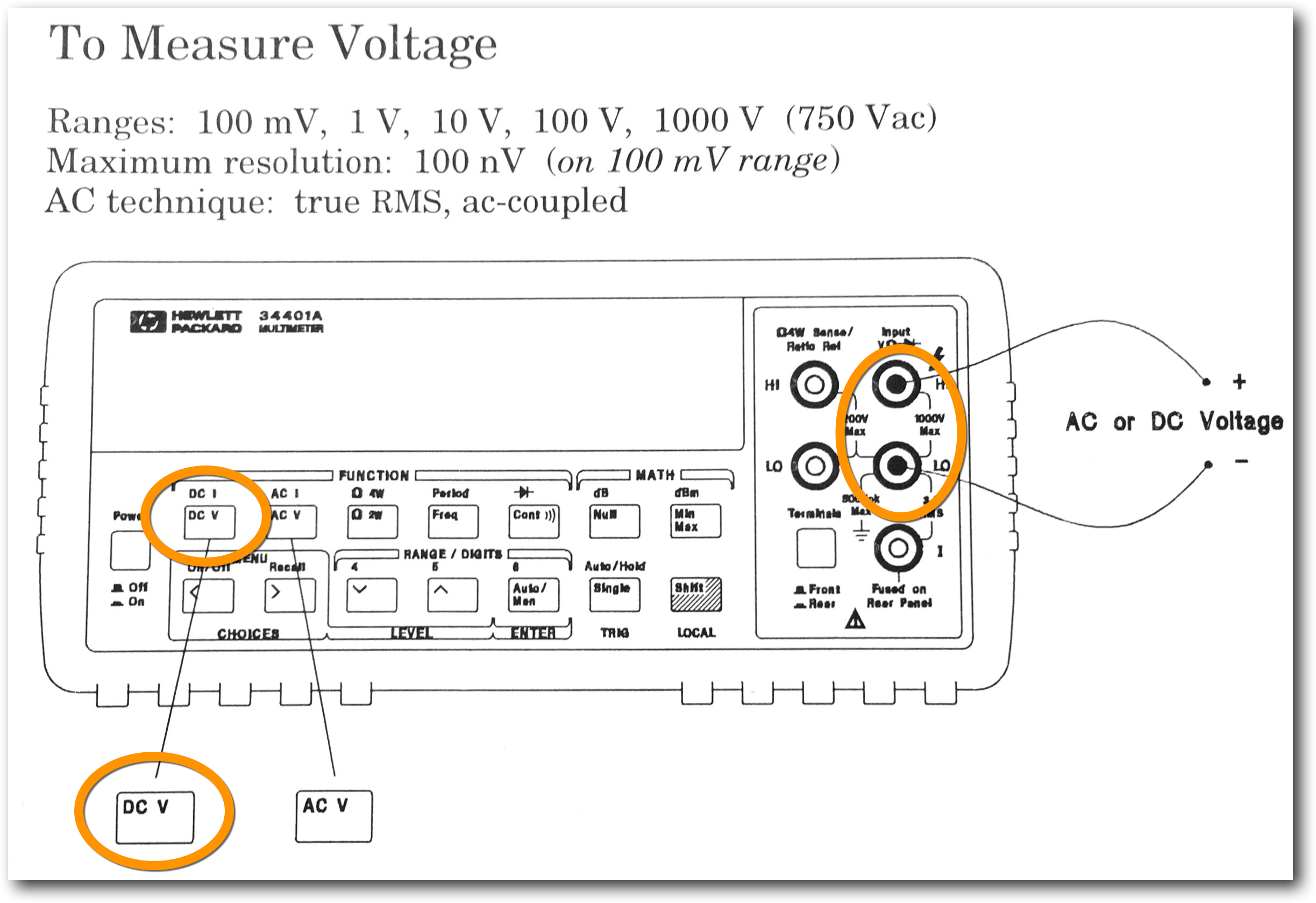
[[Image:AgilentVoltmeter.png |600px|center]] | [[Image:AgilentVoltmeter.png |600px|center]] | ||
<br /> | <br /> | ||
| + | * Press the '''DC V''' button, and plug a black probe (rubber banana plug) into the '''LO''' connector (refer to diagram above), and a red probe (rubber banana plug) into the '''HI''' connector. | ||
| + | * Press the '''Auto/Man''' button to put the meter into '''Automatic''' range measurements. | ||
Revision as of 14:59, 9 February 2016
--D. Thiebaut (talk) 14:43, 9 February 2016 (EST)
Electronics, Diodes, and Transistors
Part 1: Ohm's Law
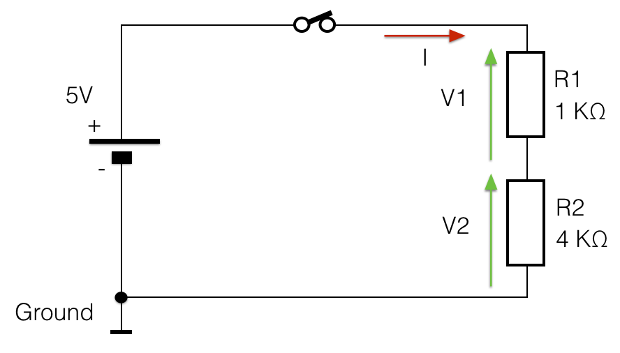
- For this part, you will implement the circuit below on the breadboard and you will measure V1 and V2 (see more information about the voltmeter below). Verify that V1 + V2 = 5 V and that V1/R1 = V2/R2.
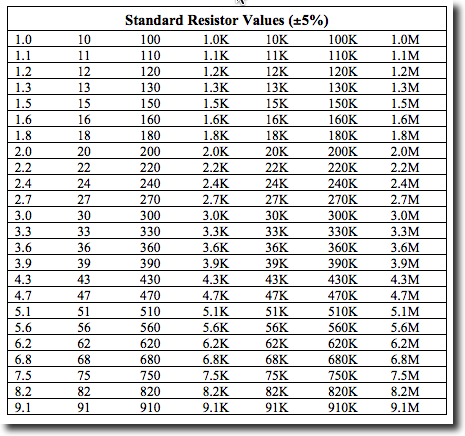
- You may not be able to find a 4 KOhm resistor, but most likely a 3.9 KOhm one. (See chart below, taken from ecee.colorado.edu/~mcclurel.
Measuring Voltages with the Agilent 34401A Voltmeter
- Press the DC V button, and plug a black probe (rubber banana plug) into the LO connector (refer to diagram above), and a red probe (rubber banana plug) into the HI connector.
- Press the Auto/Man button to put the meter into Automatic range measurements.


