Difference between revisions of "CSC270 Lab 3 2016"
| Line 64: | Line 64: | ||
==Transistor as Inverter== | ==Transistor as Inverter== | ||
<br /> | <br /> | ||
| − | * Implement the circuit below, using a | + | * Implement the circuit below, using a 2N5772 transistor. The pin labeling of the 2N5772 is given in the diagram, to the right. |
* Connect the inputs of the AND gate to a Logic Switch. Connect the output of the transistor (Collector) to a Logic Indicator. | * Connect the inputs of the AND gate to a Logic Switch. Connect the output of the transistor (Collector) to a Logic Indicator. | ||
* Connect the output of the AND gate to a Logic Indicator. | * Connect the output of the AND gate to a Logic Indicator. | ||
Revision as of 15:04, 11 February 2016
--D. Thiebaut (talk) 14:43, 9 February 2016 (EST)
This lab will introduce you to electricity and electronic components, such as the resistor, the diode, and the transistor. Make sure you demonstrate the different circuits you wire up.
Contents
Part 1: Ohm's Law
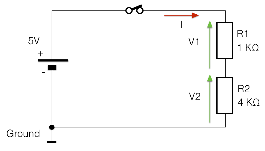
- For this part, you will implement the circuit below on the breadboard and you will measure V1 and V2 (see more information about the voltmeter below). Verify that V1 + V2 = 5 V and that V1/R1 = V2/R2.
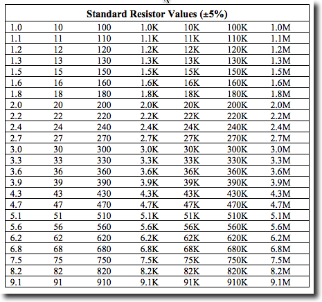
- You may not be able to find a 4 KOhm resistor, but most likely a 3.9 KOhm one. (See chart below, taken from ecee.colorado.edu/~mcclurel.
Measuring Voltages with the Agilent 34401A Voltmeter
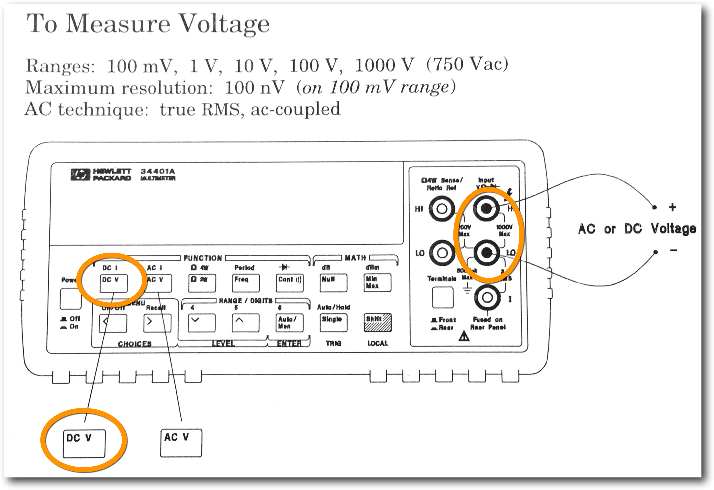
- Press the DC V button, and plug a black probe (rubber banana plug) into the LO connector (refer to diagram above), and a red probe (rubber banana plug) into the HI connector.
- Press the Auto/Man button to put the meter into Automatic range measurements.
- In your lab report, indicate the 3 voltages measured: V, V1, and V2.
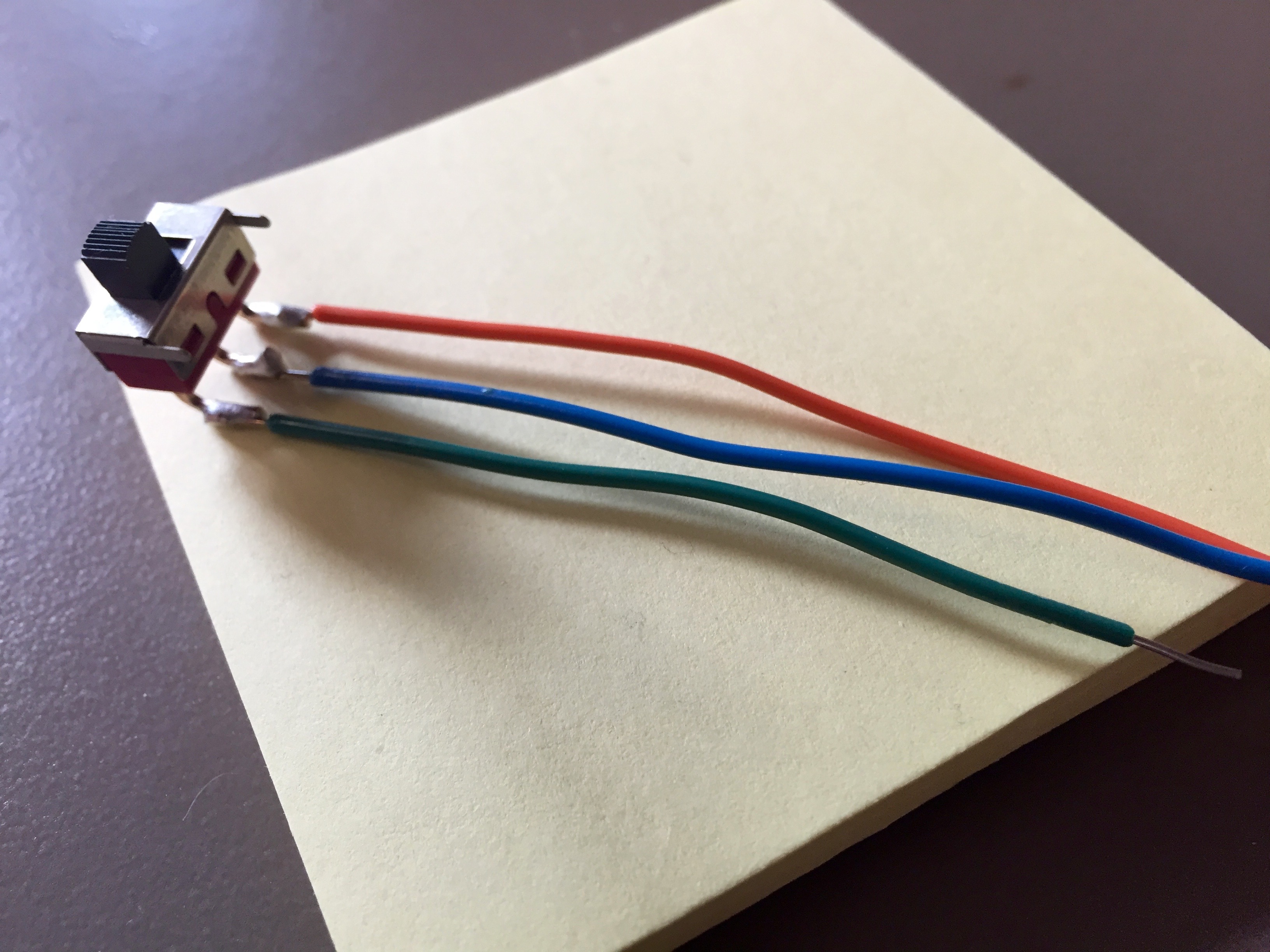
Creating Your Own Input Switch
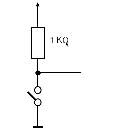
- Implement the circuit below, and connect its output to a Logic Indicator. Use a switch from one of the drawers on the North wall of the room. There are 2 drawers, one labeled "Switches" and one labeled "Push Buttons". Switches are better, although a push button would do as well.
- Verify that you can generate a 0 and a 1 with your switch.
Light-Emitting Diodes (LED)
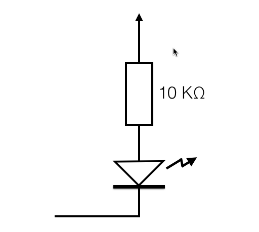
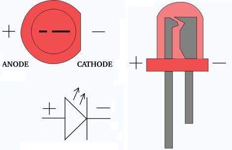
- Implement the circuit below, which uses an LED. The diagram on the right indicates how to find the polarity of the LED.
- Connect the input of the circuit (left line) to a Logic Switch. Connect one of the Logic Indicators on the Kit to the same Logic Switch.
- Comment on your circuit. Is it working the way you want? Why or why not?
|
|
- Fix the circuit by adding the appropriate gate.
Transistor as Inverter
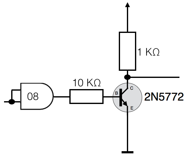
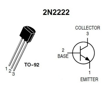
- Implement the circuit below, using a 2N5772 transistor. The pin labeling of the 2N5772 is given in the diagram, to the right.
- Connect the inputs of the AND gate to a Logic Switch. Connect the output of the transistor (Collector) to a Logic Indicator.
- Connect the output of the AND gate to a Logic Indicator.
- Verify that the transistor inverses the signal it receives.
|
|
Mystery Gate
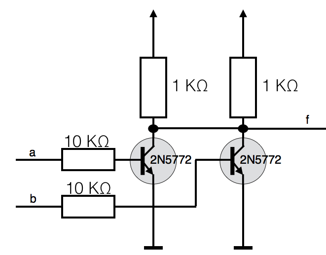
- Implement the TTL (transistor-transistor logic) gate below.
- Connect the inputs (on the left) to two Logic Switches, and the output to a Logic Indicator.
- Generate its truth table
- Identify the gate.
