Difference between revisions of "CSC103 2011 Lab 3"
(→Solution) |
(→Solution) |
||
| Line 197: | Line 197: | ||
==Solution== | ==Solution== | ||
Highlight the text in the box below to see the solution. | Highlight the text in the box below to see the solution. | ||
| − | <font color="white"> | + | <font color="white"> |
| − | |||
0 LOD 10 | 0 LOD 10 | ||
1 ADD 10 | 1 ADD 10 | ||
| Line 206: | Line 205: | ||
... | ... | ||
10 1 | 10 1 | ||
| − | + | </font> | |
| − | </font> | ||
=Part 8: A new instruction: JMZ= | =Part 8: A new instruction: JMZ= | ||
Revision as of 18:46, 13 February 2011
--D. Thiebaut 20:59, 8 February 2011 (EST)
<meta name="keywords" content="computer science, How Computers Work, Dominique Thiebaut, smith college" /> <meta name="description" content="Dominique Thiebaut's Web Page" /> <meta name="title" content="Dominique Thiebaut -- Computer Science" /> <meta name="abstract" content="Dominique Thiebaut's Computer Science Web pages" /> <meta name="author" content="thiebaut at cs.smith.edu" /> <meta name="distribution" content="Global" /> <meta name="revisit-after" content="10 days" /> <meta name="copyright" content="(c) D. Thiebaut 2000, 2001, 2002, 2003, 2004, 2005, 2006, 2007,2008" /> <meta name="robots" content="FOLLOW,INDEX" />
Contents
- 1 Part 1: Starting the simulator
- 2 Part 2: Loading a constant in the Accumulator
- 3 Part 3: Loading a number in a memory word
- 4 Part 4: A program that adds two numbers together
- 5 Part 5: Exercise #1
- 6 Part 6: A program with a new instruction: JMP
- 7 Part 7: Exercise #2
- 8 Part 8: A new instruction: JMZ
- 9 Part 9: Challenging Problem of the day
- 10 Part 10: What is it?
In this lab you will program at the lowest level of programmation: at the assembly language level. You will write small programs in assembly, and see how the programs correspond to numbers that are stored in memory. Some numbers represent instructions, some numbers represent data. But everything in memory is a number! That's a very important concept of CSC103!
Part 1: Starting the simulator
- Go to the applet page for the class. Click on
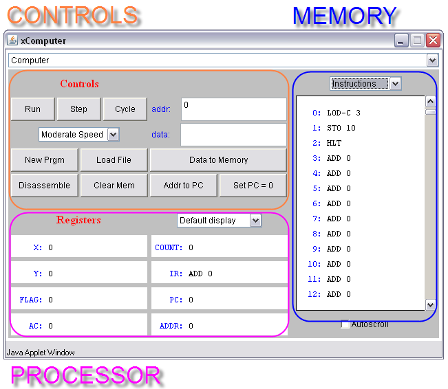
- The processor simulator will pop up.
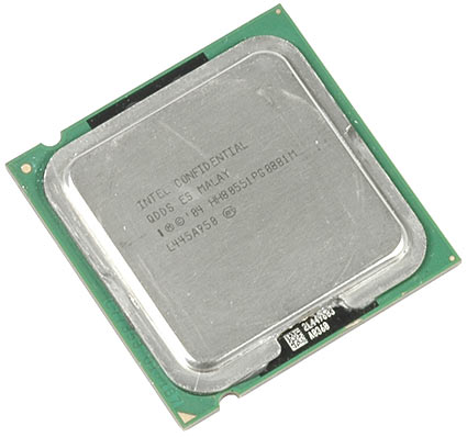
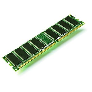
The purple part represents what is inside the processor, while the blue part represents the memory. Remember what they look like from the recent lab:
| Processor | Memory | |
|---|---|---|
|
|
Part 2: Loading a constant in the Accumulator
- First, make sure the top right box displays Instructions as the format of the data in memory.
- Let's write a 1-instruction program:
0   LOD-C   57
1   HLT
- Enter 0 in the addr: box, and LOD-C 57 in the data: box. Press Enter to store these values in memory.
- Enter 1 (if it isn't already there) in the addr: box, and HLT in the data: box. Press Enter to store these values in memory.
- Make sure the Program Counter is set to 0, otherwise click on the special button for that purpose.
- Run your program by clicking on the Cycle a few times.
- Verify that you get the right number in the accumulator register.
Part 3: Loading a number in a memory word
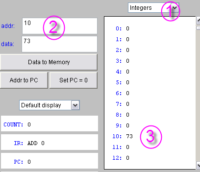
- First make sure that the top right box displays Integers as the format of the data in memory.
- In the same addr: and data: boxes, enter 10 (for the address), and 73 (for the data). Then press Enter.
- Verify that you get the number 73 at Address 10.
Part 4: A program that adds two numbers together
Now that you know how to enter instructions and data in memory, enter the following program in memory (the information following the #-signs represents comments, and shouldn't be entered in memory):
0 LOD 10        # load memory word at address 10 in accumulator
1 ADD 11        # add memory at address 11 to accumulator
2 STO 12        # store accumulator at address 12
3 HLT           # stop program
...
10  22
11  5
12  0
- Reset PC to 0
- Click Cycle regularly and observe how the processor goes to memory to fetch instructions, to decode them, and to execute them.
- Observe how the accumulator changes as the result of the execution of the instructions.
- Repeat the program a few times (by resetting PC to 0 every time) to make sure you observe everything that is changing in the processor.
- Another way of running your program is to simply reset PC to 0 and click the Run button. Try it!
Part 5: Exercise #1
Modify your program so that it starts with 3 values at Addresses 10, 11, and 12, and it computes their sum and stores the result at Address 13.
For example, if you start with the following memory contents:
10   22
11    7
12    3
13    0
Then after running your program your memory will contain:
10   22
11    7
12    3
13   32
Solution
Highlight the text in the box to see the solution!
0 LOD 10
1 ADD 11
2 ADD 12
3 STO 13
4 HLT
...
10 22
11 7
12 3
13 0
Part 6: A program with a new instruction: JMP
- Enter the following program in memory:
0 LOD 10
1 ADD-C 1
2 STO 10
3 JMP 0
4 HLT
...
10 0
- Set PC to 0
- Select Integers as the format for displaying the contents of the memory
- Run the program.
- Keep on observing the program!
- What is the behavior of the program?
- What do we call such a program? (Check with your instructor or the TA if you have figured out the right answer.)
- You may find the Stop button useful for this exercise!
- You will have figured out that the JMP instruction stands for JUMP, and forces the processor to jump back to a particular address in memory. In this case it tells the processor JUMP BACK TO ADDRESS 0.
- How does the processor actually go back to Address 0?
Part 7: Exercise #2
- Modify the above program so that the number in Memory Address 10 is 1 at the beginning, then 2, then 4, then 8, then 16, then 32, etc...
- In case you were wondering what other instructions are available, you can find a list here.
Solution
Highlight the text in the box below to see the solution.
0 LOD 10
1 ADD 10
2 STO 10
3 JMP 0
4 HLT
...
10 1
Part 8: A new instruction: JMZ
- The JMZ instruction is the JUMP IF ACC IS 0 instruction. It means, Processor, jump to the address indicated on the same line if the accumulator contains 0, otherwise continue on with the next instruction.
- Assume that the program contains the following instruction at Address 3:
    2  ...
    3  JMZ 5
    4  ...
    5  ...
- When the processor executes this instruction, it looks at the contents of the ACCumulator, and if the number there is 0, the processor then jumps to Address 5. If the ACCumulator does not contain 0, then the processor continues on with the following instruction at Address 4.
- Check it out! Enter the following program in memory
 0 LOD 10
 1 SUB-C 1
 2 STO 10
 3 JMZ 5
 4 JMP 0
 5 HLT
 ...
 10  5
- Set the memory display to Numbers.
- Run the program.
- What happens? Why?
- What if we had stored 7 at Address 10? What would have happened then?
- Try it out, and see if your intuition was right!
Part 9: Challenging Problem of the day
- Write a program that stores the following values successively in memory at address 11: 1, 2, 4, 8, 16, and 32, and then stops.
- This is quite challenging! Make sure you work in groups and share your intuition with other people around you to come up with something that will work.
Solution
0 LOD 10
1 ADD 10
2 STO 10
3 SUB-C 32
4 JMZ 6
5 JMP 0
6 HLT
...
10 1
Part 10: What is it?
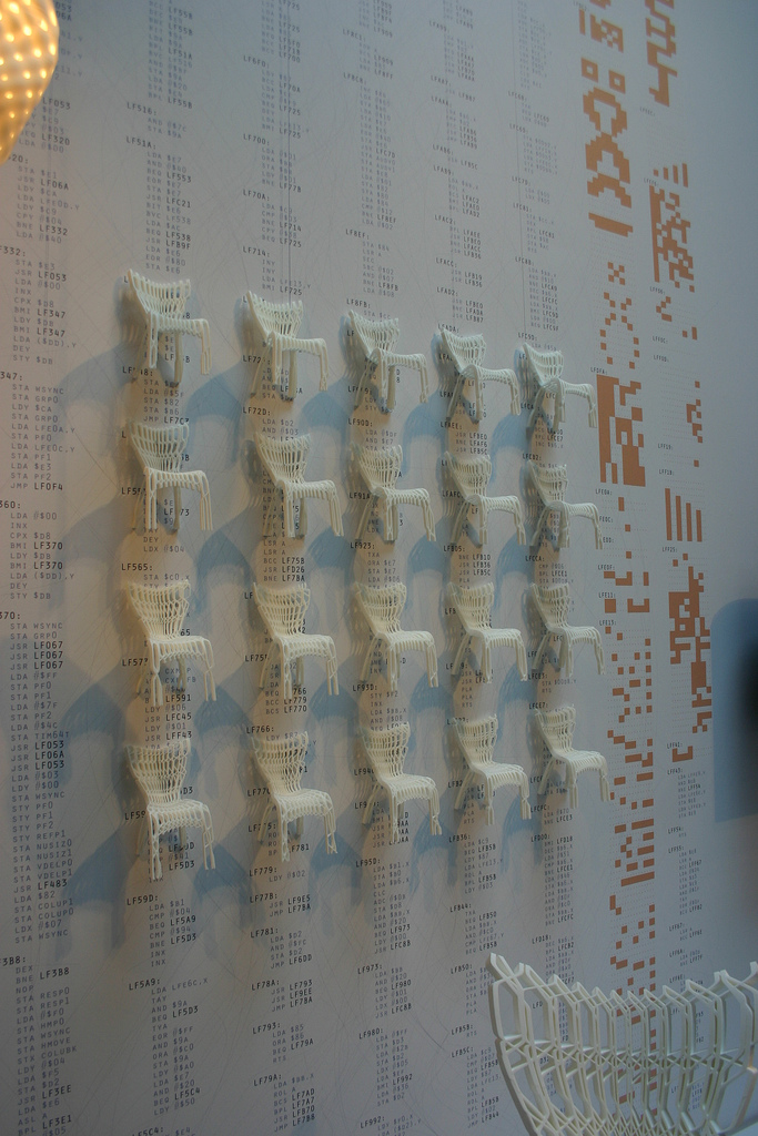
The picture below was taken at the exhibit Design and the Elastic Mind that was at MoMA, in NYC last year. It was an exhibit exploring the links between art, design, science and computers.
What is interesting about the picture? Can you spot a relationship with our class? No? Look more closely! :-)
You can find more pictures of this exhibit on Flickr
