Difference between revisions of "CSC270 Lab 6 2011"
(→1-Flipflop Sequencer/Oscillator) |
(→LAB #6: The 74LS74 D-Flip-Flop) |
||
| Line 7: | Line 7: | ||
=LAB #6: The 74LS74 D-Flip-Flop= | =LAB #6: The 74LS74 D-Flip-Flop= | ||
| + | |||
| + | <font color="magenta">(This part should have already been done last week and is reported here for completeness)</font> | ||
The [http://cs.smith.edu/~thiebaut/classes/270/datasheets/sn74ls74arev5.pdf 74LS74] chip contains two flip-flops: | The [http://cs.smith.edu/~thiebaut/classes/270/datasheets/sn74ls74arev5.pdf 74LS74] chip contains two flip-flops: | ||
Revision as of 23:48, 27 February 2011
--D. Thiebaut 22:58, 27 February 2011 (EST)
Contents
LAB #6: The 74LS74 D-Flip-Flop
(This part should have already been done last week and is reported here for completeness)
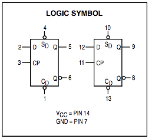
The 74LS74 chip contains two flip-flops:
- Put one on your bread board, and connect Preset and Clear to two switches, D to another switch, and Clock to the 1Hz clock signal.
- Set both Preset and Clear to 1.
- Connect D, Clock, Q, and Q-bar to 4 LEDs.
- Slowly change the D input from low to high and observe how the signals change.
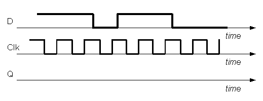
- From your observations, complete the timing diagram below so that we can see how Q and Q-bar change, according to your observations, not to what you think should happen.
Clear active
Same question, but this time you will set the Clear input to 0.
Preset active
Same question, but this time you will set the Preset input to 0 (and return Clear to 1).
1-Flipflop Sequencer/Oscillator
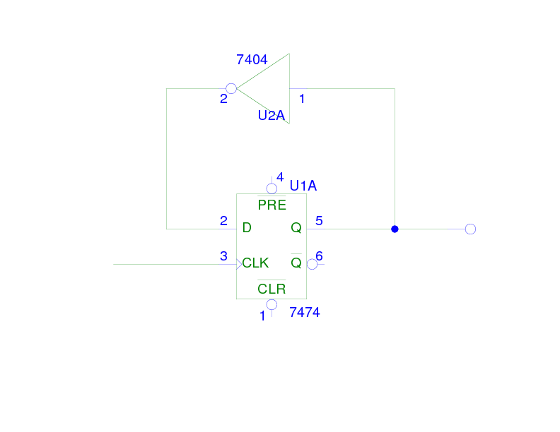
Implement the circuit below:

Connect both the Clock and Q signals to logic indicators.
- What is the frequency at which the Q output oscillates?
- What is the relationship between the frequency of Q and the frequency of the clock input? Does the 74LS74 wired this way behave as a frequency multiplier or a frequency divider?
- Draw the state diagram of this finite-state machine (FSM).
- Implement and wire-up a divide-by-4 frequency divider. Demonstrate that it works!
2-Flip-Flop Sequencer
Machine 1
- Build a state-machine with 2 flip-flops. Flip-flop 1 has input D1 and outputs Q1 and Q1'. Flip-flop 2 has input D2 and outputs Q2 and Q2'.
- Perform the following connections.
- D1 = Q0
- D0 = Q1 NOR Q0
- Connect the Pr1, Pr0 inputs to a momentary switch with a default high level.
- Connect the Pr1, Pr0 inputs to another momentary switch with a default high level.
- Connect the two clock signals to the 1 Hz clock signal.
- Connect Q0 and Q1 to two LEDs
- Question 1
- How many states does your machine have?
- Question 2
- Activate the momentary switch that is connected to the Preset inputs. What happens with Q1 and Q0
- Question 3
- Again, how many different states does your machine have?
Machine 2 (time permitting)
- Change the connections so that the equations for D1 and D0 become:
- D1 = Q0
- D0 = NOT ( Q1 XOR Q0 )
- Question 1
- How many states does your machine have?
- Question 2
- Activate the momentary switch that is connected to the Preset inputs. What happens with Q1 and Q0
- Question 3
- Again, how many different states does your machine have?

