Difference between revisions of "CSC270 Homework 9 Solutions 2012"
(Created page with "--~~~~ ---- <onlysmith> =Problem 1= The trick was to figure out the decoding of the address bus. * For Y3' to be activated, the 7442 signals need to be: A3 = 0, A2 = 0, A1 = 1, ...") |
|||
| Line 52: | Line 52: | ||
=Problem 3= | =Problem 3= | ||
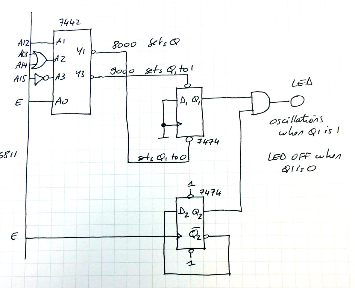
For this problem, we can use the setup of Problem #2, and use the output of the flip-flop to enable or disable a 500 KHz signal to reach the LED. This 500 KHz signal is simply E divided by 2. The figure below illustrates the whole thing. | For this problem, we can use the setup of Problem #2, and use the output of the flip-flop to enable or disable a 500 KHz signal to reach the LED. This 500 KHz signal is simply E divided by 2. The figure below illustrates the whole thing. | ||
| − | <center>[[Image:CSC270Hw9Pro3Sol2012.png]]</center> | + | <center>[[Image:CSC270Hw9Pro3Sol2012.png|700px]]</center> |
<br /> | <br /> | ||
Revision as of 16:08, 21 April 2012
--D. Thiebaut 16:55, 21 April 2012 (EDT)
<onlysmith>
Problem 1
The trick was to figure out the decoding of the address bus.
- For Y3' to be activated, the 7442 signals need to be: A3 = 0, A2 = 0, A1 = 1, and A0 = 1 (since 3 = 0011 in binary).
- A3 = 0 means A15 = 1
- A2 = 0 means A14 and A13 are both 0
- A1 = 1 means A12 = 1
- A0 = 1 means E = 1, i.e. 2nd half of a cycle.
- A15 14 13 12 = 1 0 0 1 = 9 in hex.
- So 9000 to 9FFF are addresses that will latch Data Bus Bit 1 in the flip flop.
- To store a 1 we need to put 1 on D1: 02 in hex
- To store a 0 we need to put 0 on D1.
             ORG 0000
TurnON:
             ldaa #2
stoff:       staa 9000
             rts

TurnOFF:
             ldaa #0
             bra  stoff
Problem 2
Using the same decoding of the Address Bus as above, we find that Y3' is activated by 9000, and Y1' by 8000.
- Y3' activates the preset signal, so it will set the LED ON
- Y1' activates the clear signal, so it will set the LED OFF
- Since the data bus is not connected to the flip-flop, it doesn't matter what we put on the data bus, as long as 8000 or 9000 appear on the address bus. Actually, it doesn't even matter whether we read or write from these addresses.
             ORG 0000
TurnON:
             ldaa 9000
             rts

TurnOFF:
             ldaa 8000
             rts
Problem 3
For this problem, we can use the setup of Problem #2, and use the output of the flip-flop to enable or disable a 500 KHz signal to reach the LED. This 500 KHz signal is simply E divided by 2. The figure below illustrates the whole thing.
