Difference between revisions of "CSC103 Examples of Schematics with Logic Gates"
| Line 1: | Line 1: | ||
--[[User:Thiebaut|D. Thiebaut]] 13:57, 27 September 2012 (EDT) | --[[User:Thiebaut|D. Thiebaut]] 13:57, 27 September 2012 (EDT) | ||
---- | ---- | ||
| + | |||
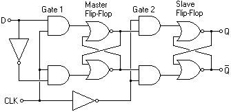
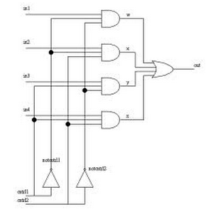
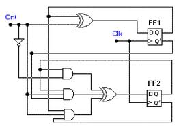
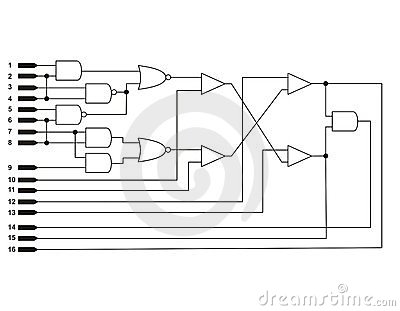
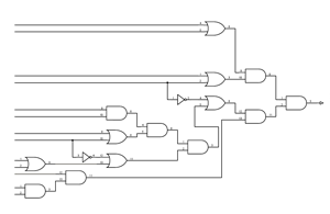
| + | Notice the rules the engineers use to draw their diagrams: | ||
| + | * the information normally flows from left to right | ||
| + | * the wires rarely go "backward" from a the output of a gate that is more to the input of a gate that would be to its left. | ||
| + | * the wires are most often horizontal or vertical. | ||
<center> | <center> | ||
Revision as of 13:02, 27 September 2012
--D. Thiebaut 13:57, 27 September 2012 (EDT)
Notice the rules the engineers use to draw their diagrams:
- the information normally flows from left to right
- the wires rarely go "backward" from a the output of a gate that is more to the input of a gate that would be to its left.
- the wires are most often horizontal or vertical.
