Difference between revisions of "CSC231 Lab 5"
(→Option 2: +5V to resistor to LED to output) |
(→Option 2: +5V to resistor to LED to output) |
||
| Line 68: | Line 68: | ||
* Make sure you explain in your report the difference between the two wiring approaches. | * Make sure you explain in your report the difference between the two wiring approaches. | ||
| − | |||
| − | |||
<br /> | <br /> | ||
<br /> | <br /> | ||
Revision as of 09:17, 3 October 2008
 Back to CSC231 Weekly Schedule
Contents
CSC 231 Lab # 5
© D. Thiebaut, 2008
This lab is designed to make you interface simple input and output devices to the Arduino.
Introduction to Electricity and Electronics
Stay tuned for a presentation at the board of the following basic principles:
- The output of a logic gate: high and low voltages
- Resistors
- Diodes
- switches
- buzzer
Do not move on to the next section until this section has been presented
Lab report
Write up your lab report as part of your 231a Wiki page. Feel free to take pictures of your kits and use them to illustrate your report. This will be the "theoretical" part of your final project: an explanation of how to wire-up hardware to the Arduino board.
Resistors
Find a good reference for the color coding of resistor. The first person to find a good reference should share it with the class by adding it to the reference section of the CSC231 Wiki portal.
Connecting an LED to Pin 13
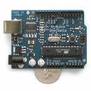
Look at the schematics of the Arduino. Locate Pin 13. Observe that it is already connected to an on-board LED. You are going to attach another LED to the same output, Pin 13.
Option 1: Output to LED, to resistor, and to GND
- Turn off the Arduino by disconnecting it from the USB cable.
- Locate the +5V, GND, and #13 pins on the Arduino side connector. Be careful, it is easy to put a wire in the wrong hole.
- Create your circuit following the diagram on the right with one LED and one 1KOhm resistor on the digital kit (anything between 1KOhm and 20KOhm should work).
- Use the 5V and GND of the Arduino, not those of the Kit.
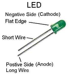
- Once you have your circuit wired up, power up the Arduino and download the Blink sketch. Does your LED blink? If not, turn it around and reverse its polarity.
- Indicate on your report what is the right way to wire up an LED.
- Does it blink in phase or out of phase with the on-board LED?
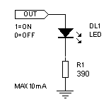
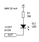
Option 2: +5V to resistor to LED to output
- Same steps as in the previous section, but use the picture on the right as the example.
- Same question: is your LED blinking in phase or out of phase with the on-board LED?
- Make sure you explain in your report the difference between the two wiring approaches.
Connecting an LED to Pin 11
- Change the sketch so that it make your LED blink.
- Modify the sketch so that the on-board LED blinks at 0.5 Hz and your new LED blinks at 1 Hz.
- Make your LED blink as fast as possible. How fast is it blinking? How can you find out? How can you measure this frequency precisely? Be imaginative
Replace the LED and Resistor with a buzzer
Connect a switch to Pin 11
- First disconnect all hardware from your Arduino
- Modify your sketch and make Pin 11 an input pin.
- Download your sketch to the Arduino
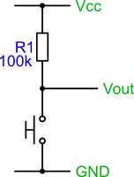
- Now that the pin is programmed as an input, use the circuit we will have seen in class to connect a switch (with a resistor) to the Pin 11.
- Change your sketch so that you can turn the LED connected to Pin 13 ON or OFF with the switch.
- Make the sketch increment a counter every time your switch is found to have changed state. Make the Arduino display the counter on the PC screen. Activate the switch ON and OFF quickly. Is the Arduino keeping the right count? Why or why not?
Misc. References
- Debouncing a switch, from www.bioinspired.com
