Difference between revisions of "CSC231 Homework 7"
(→Arduino Project Schematics) |
|||
| Line 1: | Line 1: | ||
(c) --[[User:Thiebaut|DT]] 13:42, 30 October 2008 (UTC) | (c) --[[User:Thiebaut|DT]] 13:42, 30 October 2008 (UTC) | ||
| − | =Arduino Project Schematics= | + | =Problem #1: Arduino Project Schematics= |
I would like you to generate a diagram showing all the hardware parts you will be using for your project, and how they are connected to each other. This diagram should clearly show the Arduino board as a box with lines going in and out of it, with arrows indicating whether the signals are inputs or outputs, and the pin numbers. Resistors, switches and other parts should be clearly indicated, with their values and part numbers if you have them. | I would like you to generate a diagram showing all the hardware parts you will be using for your project, and how they are connected to each other. This diagram should clearly show the Arduino board as a box with lines going in and out of it, with arrows indicating whether the signals are inputs or outputs, and the pin numbers. Resistors, switches and other parts should be clearly indicated, with their values and part numbers if you have them. | ||
| Line 44: | Line 44: | ||
|} | |} | ||
| + | =Problem #2= | ||
| + | |||
| + | Stay tuned... | ||
Revision as of 09:13, 30 October 2008
(c) --DT 13:42, 30 October 2008 (UTC)
Problem #1: Arduino Project Schematics
I would like you to generate a diagram showing all the hardware parts you will be using for your project, and how they are connected to each other. This diagram should clearly show the Arduino board as a box with lines going in and out of it, with arrows indicating whether the signals are inputs or outputs, and the pin numbers. Resistors, switches and other parts should be clearly indicated, with their values and part numbers if you have them.
Below are several examples, some fancier than others. I have added comments to highlight what is good and what is missing. Use them as guidelines to generate your project diagram/schematics.
You will have questions and I do not expect you to know electronics, so do stop by my office or make an appointment to review your diagram. Once I am satisfied that your diagram is safe for the Arduino, you will have the go ahead (as soon as you get the parts) to wire it up and start concentrating on the programming side of the project.
| Diagram | Comments |
|---|---|
|
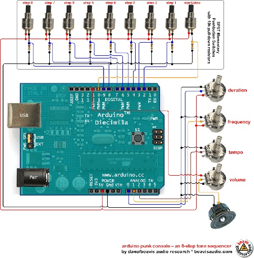
Very fancy. You don't need to be that fancy. Although this is fancy, I find it lacking in information, for example the value of the potentiometers, and the impedance of the speaker. | |
|
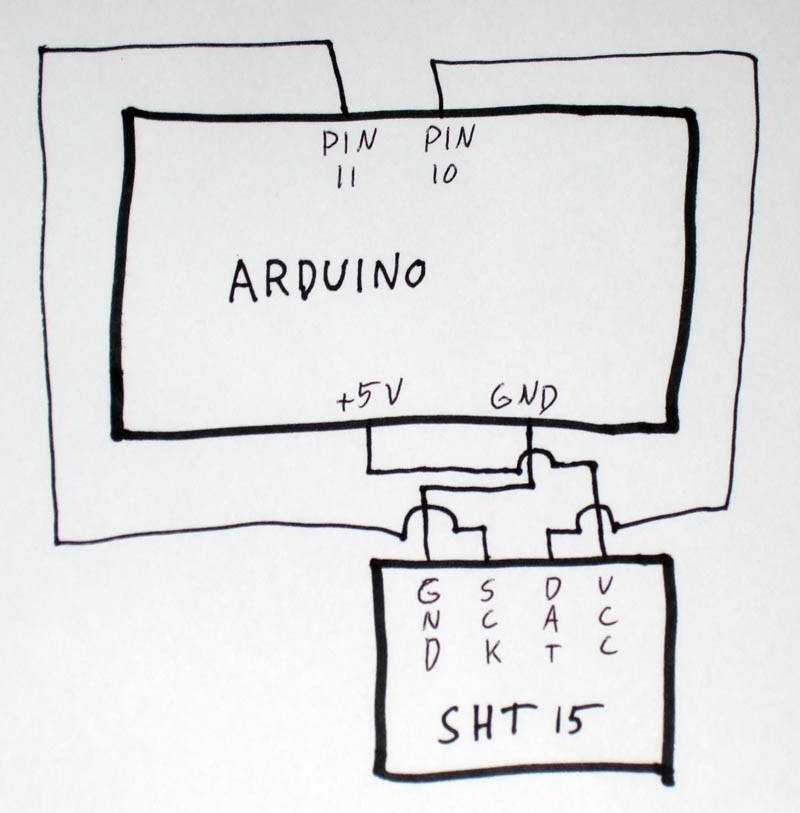
Very simple, but too crude. It doesn't have to be fancy, but I would recommend using MSWord or some drawing package to get something that is computer generated, and a bit more pleasing. The lower block should be labeled so that we have pin numbers, and its name and part number. | |
|
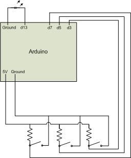
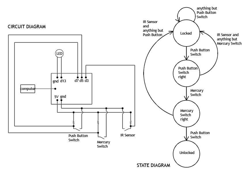
Neat. But the resistors should have values, the switches should be labeled (SW1, SW2, SW3), and the LED should be labeled as well (LED1). I would add arrows on the lines arriving at d13, d7, d5 and d3 to indicate which of them are outputs and which are inputs. | |
|
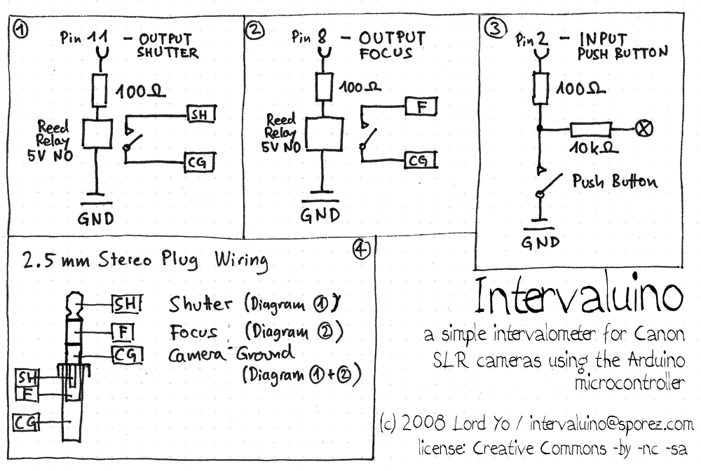
When diagrams are drawn by hand nicely, we have an effective diagram. Here the person didn't show the arduino, but showed the value of the resistors. I would prefer to see the connections to the Arduino. I would label the resistors (R1, R2, etc.). Note that this is a rare diagram where each pin is identified as an input or output. | |
|
Nice graphical representation showing also a state diagram. You can do the right-most diagram at some point, when you are programming. It's not needed now. Note that the Arduino is represented simply. Input/Output information is missing. Resistors should have labels and values. Note how simple the connection to the computer is shown, effectively and simply. | |
|
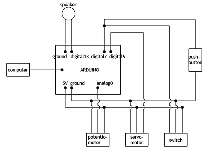
Another interesting diagram. Here the user uses boxes for everything, which is fine. But some important details are missing (resistors, etc.). |
Problem #2
Stay tuned...
