Difference between revisions of "CSC103 Logic Lab 2014"
(Created page with "--~~~~ ---- =The Logic Simulator= <br /> <center>700px</center> <br /> <br /> <br /> <br /> <br /> <br /> <br /> <br /> <br /> <br /> <...") |
(→The Logic Simulator) |
||
| Line 1: | Line 1: | ||
--[[User:Thiebaut|D. Thiebaut]] ([[User talk:Thiebaut|talk]]) 13:15, 24 August 2014 (EDT) | --[[User:Thiebaut|D. Thiebaut]] ([[User talk:Thiebaut|talk]]) 13:15, 24 August 2014 (EDT) | ||
---- | ---- | ||
| − | =The Logic Simulator= | + | =The Simple Logic Simulator (SLS)= |
<br /> | <br /> | ||
<center>[[Image:DTLogicSimulatorMainBlock.jpg|700px]]</center> | <center>[[Image:DTLogicSimulatorMainBlock.jpg|700px]]</center> | ||
<br /> | <br /> | ||
| + | THe Simple Logic Simulator is a Javascript simulator written with the [http://www.gwtproject.org/ Google WebKit] library, by D. Thiebaut. It allows for the logic design of simple logic circuits using inverters, AND gates, and OR gates. It sports 4 inputs switches and 4 output LEDs. | ||
<br /> | <br /> | ||
| + | ; The switches | ||
| + | : The switches are used to generate binary signals with the value 0 or 1. When the switch is grey (OFF), it generates a 0, and when red (ON), it generates a 1. A switch can be connected to multiple inputs. | ||
| + | ; Inverter Gates | ||
| + | : Click on the Inverter Gate button to position inverters on the breadboard area. | ||
<br /> | <br /> | ||
<br /> | <br /> | ||
Revision as of 12:30, 24 August 2014
--D. Thiebaut (talk) 13:15, 24 August 2014 (EDT)
The Simple Logic Simulator (SLS)

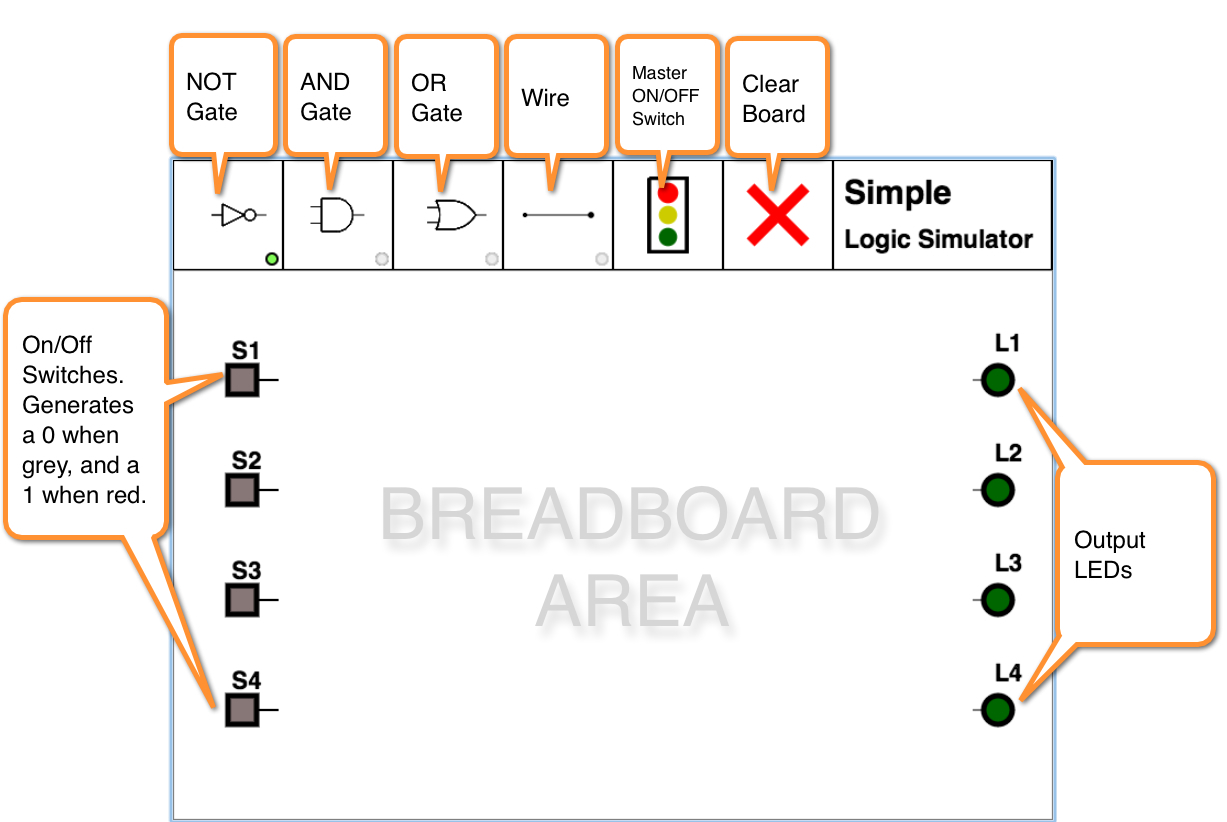
THe Simple Logic Simulator is a Javascript simulator written with the Google WebKit library, by D. Thiebaut. It allows for the logic design of simple logic circuits using inverters, AND gates, and OR gates. It sports 4 inputs switches and 4 output LEDs.
- The switches
- The switches are used to generate binary signals with the value 0 or 1. When the switch is grey (OFF), it generates a 0, and when red (ON), it generates a 1. A switch can be connected to multiple inputs.
- Inverter Gates
- Click on the Inverter Gate button to position inverters on the breadboard area.