CSC270 Lab 3 2016
--D. Thiebaut (talk) 14:43, 9 February 2016 (EST)
Contents
Electronics, Diodes, and Transistors
Part 1: Ohm's Law
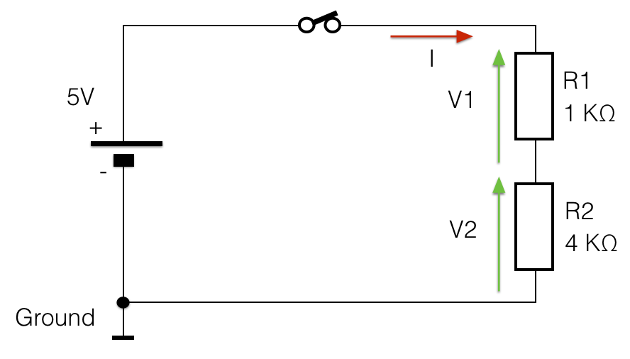
- For this part, you will implement the circuit below on the breadboard and you will measure V1 and V2 (see more information about the voltmeter below). Verify that V1 + V2 = 5 V and that V1/R1 = V2/R2.
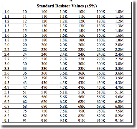
- You may not be able to find a 4 KOhm resistor, but most likely a 3.9 KOhm one. (See chart below, taken from ecee.colorado.edu/~mcclurel.
Measuring Voltages with the Agilent 34401A Voltmeter
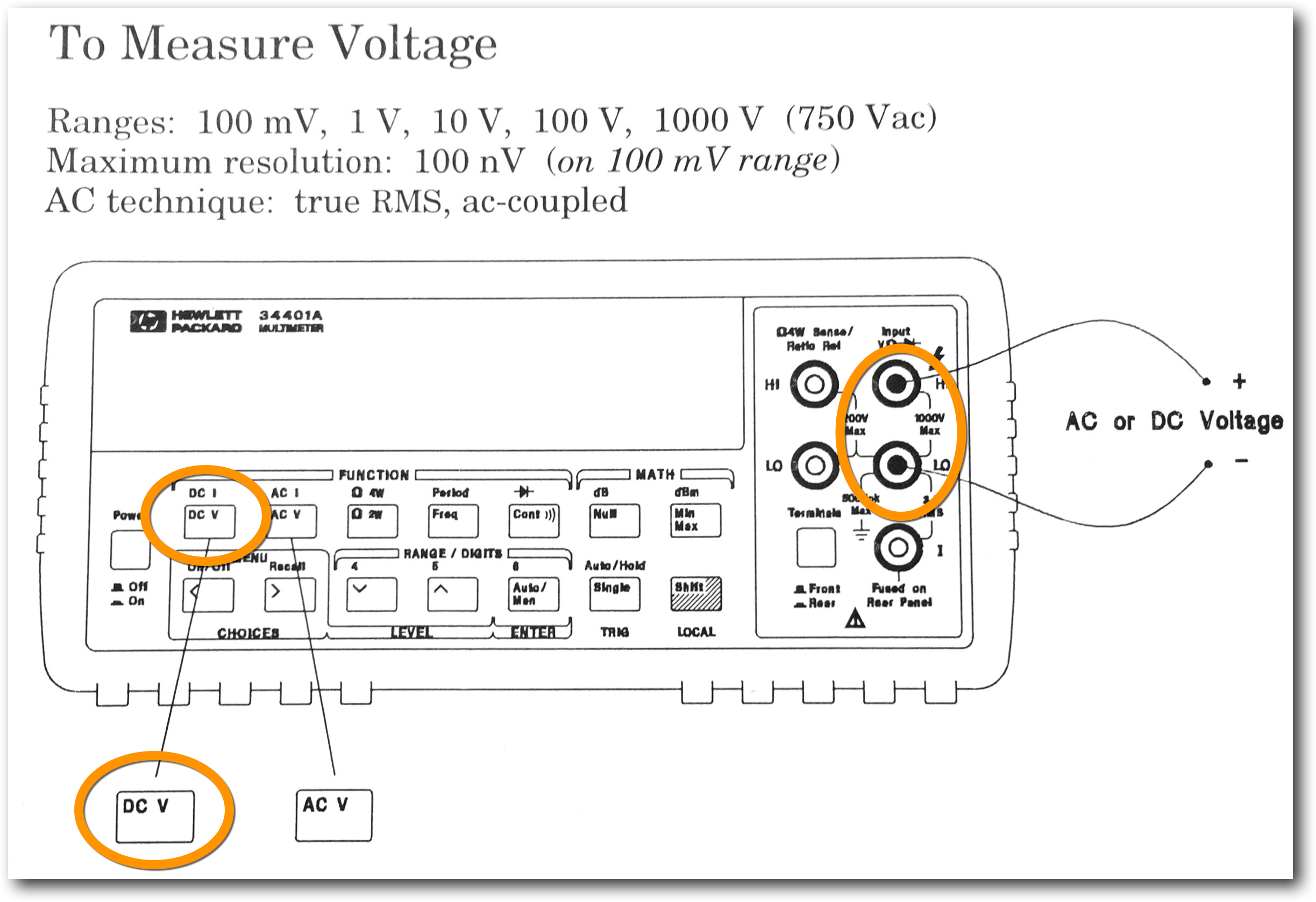
- Press the DC V button, and plug a black probe (rubber banana plug) into the LO connector (refer to diagram above), and a red probe (rubber banana plug) into the HI connector.
- Press the Auto/Man button to put the meter into Automatic range measurements.
- In your lab report, indicate the 3 voltages measured: V, V1, and V2.
Creating Your Own Input Switch
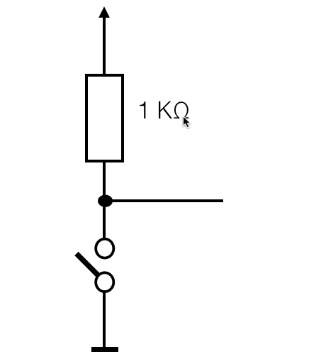
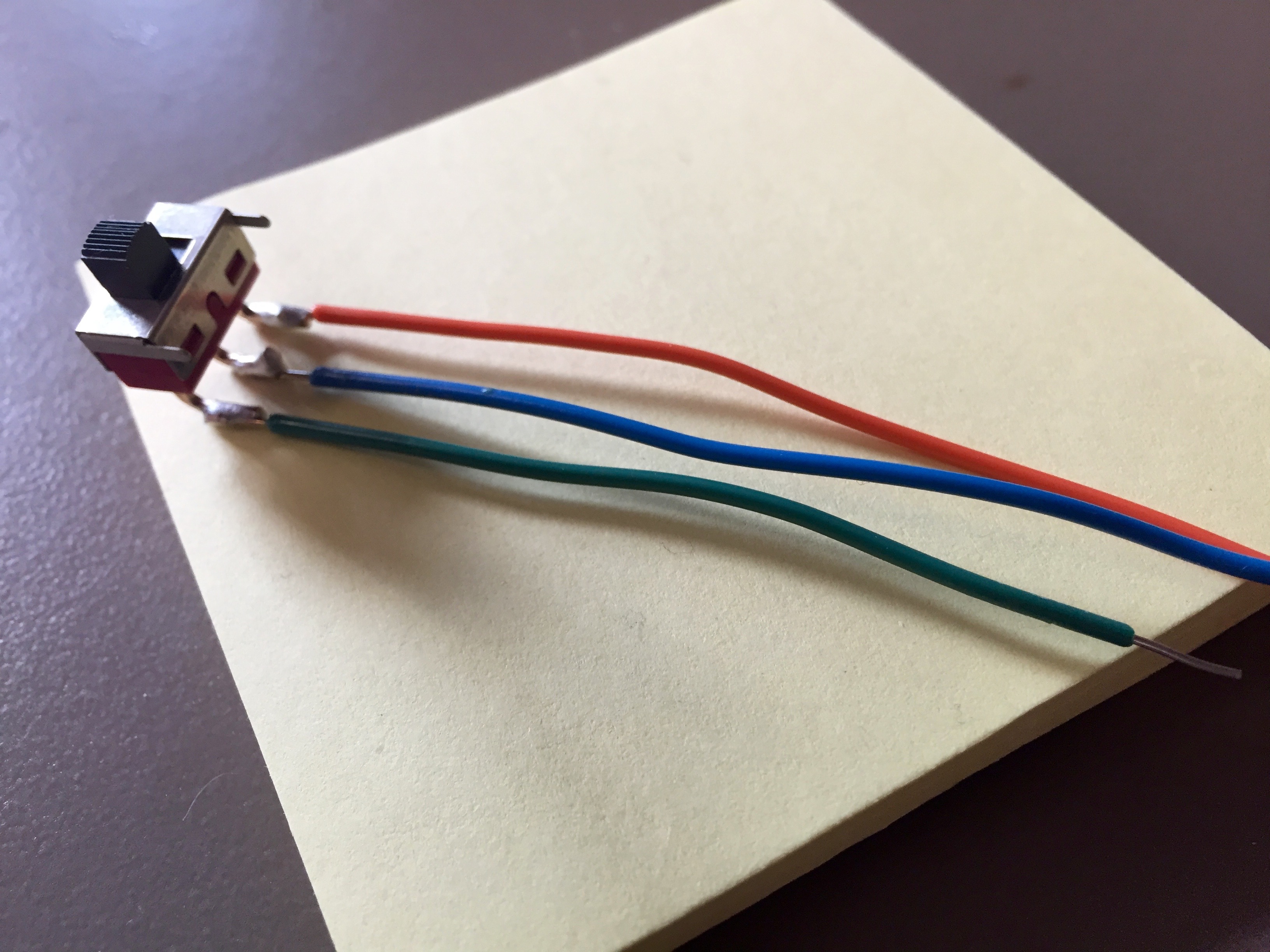
- Implement the circuit below, and connect its output to a Logic Indicator. Use a switch from one of the drawers on the North wall of the room. There are 2 drawers, one labeled "Switches" and one labeled "Push Buttons". Switches are better, although a push button would do as well.
- Verify that you can generate a 0 and a 1 with your switch.
Light-Emitting Diodes (LED)
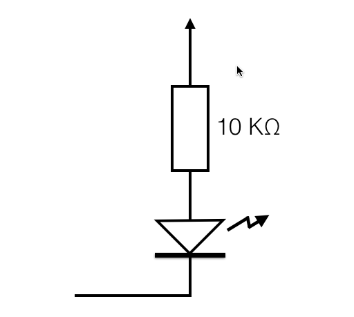
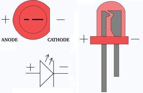
- Implement the circuit below, which uses an LED. The diagram on the right indicates how to find the polarity of the LED.
- Connect the input of the circuit (left line) to a Logic Switch. Connect one of the Logic Indicators on the Kit to the same Logic Switch.
- Comment on your circuit. Is it working the way you want? Why or why not?
|
|
- Fix the circuit by adding the appropriate gate.
Transistor as Inverter
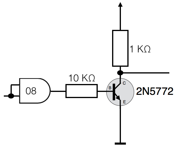
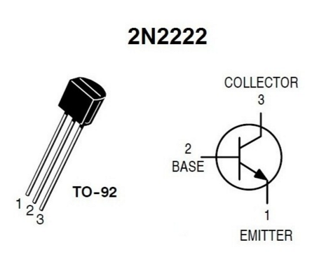
- Implement the circuit below, using a 2N2222 transistor. The pin labeling of the 2N2222 is given in the diagram, to the right.
- Connect the inputs of the AND gate to a Logic Switch. Connect the output of the transistor (Collector) to a Logic Indicator.
- Connect the output of the AND gate to a Logic Indicator.
- Verify that the transistor inverses the signal it receives.
|
|
