ABET-CSC231 Page
This page is a copy of the page at http://cs.smith.edu/classwiki/index.php/231a_ac, which was created by Yang Li for CSC231, Fall 2009.
Contents
Labs
231a-ac Lab4 Intro to Arduino
231a-ac Lab5 Input and Output with Arduino
231a-ac Lab6 Arduino and Assembly
231a-ac Lab7 Talk to Arduino
Project Pages
Proposal
Interactive LED box
Project Goal
The goal of this project is to create a low resolution display of graphical art that interacts with people who are handling it. My basic idea is to create such a "magic box" with a LED matrix on one side. It should be small enough that it can be held by hands. Also, it has to work independently from a computer, so that it be carried around. "(It will be best if the series of graphics generated by the user can be stored somewhere.)"
The basic design of input and output are the following:
- Input
- amount of tilt
- frequency of vibration (optional)
- Output
a low resolution display made of LED lights that refreshes constantly - Processing
- Store amount of tiltation and vibration(optional) in a data structure
- Visualize the data by controlling the intensity of individual LEDs.
Schematics
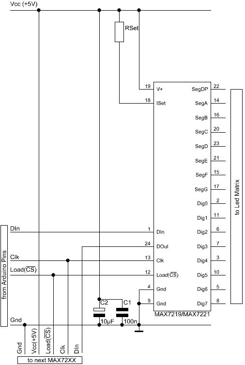
- single-color LED matrix with MAX72XX Driver
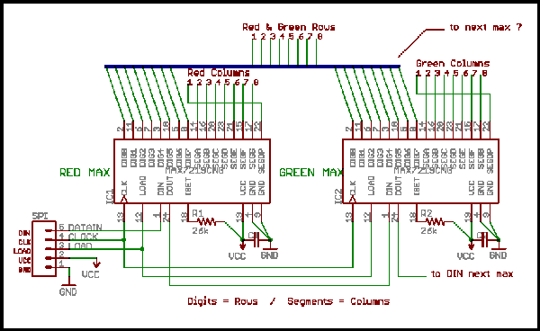
- dual-color LED matrix with 2 MAX72XX Drivers
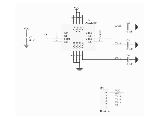
- accelerometer
Hardware List
LED matrix
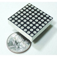
- 8x8 LED matrix display
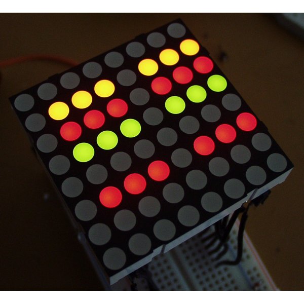
I found one with dual-color(red and green) LEDs ($4.5). With different intensity, we may get a range of pleasant colors including orange and yellow. The matrix height is 3.2in, which is the biggest among other 8x8 LED matrices with reasonable price that I could find.
LED Dot Matrix Display Red/Green #LTP2188AA LiteON
- LED display driver
LED display drivers lets you control individual LEDs easier. My two choices are either MAX7219 or MAX7221($7.02 a piece). They can drive either 64 individual Led's, or up to 8 digits of 7-segment displays. The big advantage of these drivers are that they can be controlled from the Arduino using only 3 of the digital output pins. There are also examples on driving a dual-color matrix using 2 such drivers. On the other hand, the limitation is that I couldn't use PWM(Pulse Width Modulation) to control the intensity of individual LEDs. For the dual-color LED, with PWM, I could virtually get 255*255 colors; I can only set 4 states: off, R,G,RG without PWM.
Most arduino projects uses MAX7219 and MAX7221 interchangable, while I think in my case MAX7221 would work better because of the following reason:
"The MAX7221 was designed for reduced electromagnetic interference (EMI). EMI could lead to some jitter in the readings from the analog inputs of the Arduino or if the Led matrix is placed near some audio circuit it can introduce audible noise to the signal. So, if your project would go into categories like : audio gadget, audio levelmeter, (low-)voltage measurement, etc. than better take the MAX7221. "[4]
Since my project also has analog input to sense acceleration, I'm afraid that EMI may prevent me from getting correct input from the accelerometer. MAX7219, MAX7221: Serially Interfaced, 8-Digit, LED Display Drivers
Accelerometer
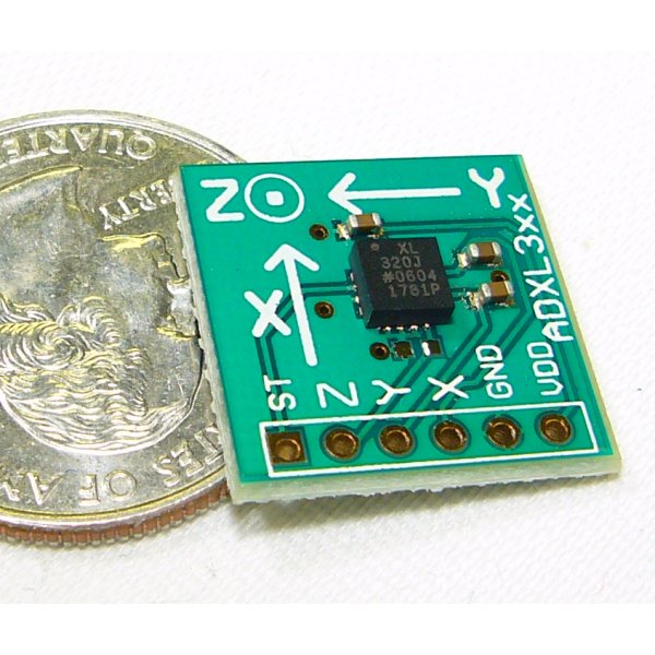
We can use the accelerometer's ability of sensing acceleration to measure a variety of things, such as acceleration (of course!), tilt angle, incline, rotation, vibration, collision detection, and gravity. In my project, I will mainly use the accelerometer to measure tilt angle.
My first choice is ADXL322, a dual-axis accelerometer (measures acceleration along x and y coordinates) with sensoring ange from -2g to 2g and analog output 0-5V. It costs about $7.95 a piece. SparkFun also sales ADXL322 breakout board. The breakout board will save a lot of wiring effort, however, it will cost $29.95, 3 times as pricy as the accelerometer alone.
Approximate Cost
- accelerometer: $7.95
- LED matrix: $4.5
- LED driver: $7.04
Total: $19.49 (shipping not included)
Resource
Schematics
Hardware
Schematics
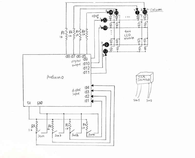
The following schematic diagram shows input/output connections from Arduino to two tilt switches and one 8*8 Green/Red LED matrix. To start with the simplest case, I will treat the LED matrix as 4*4 with single color (only use 16 green LEDs at the 4 corners of the matrix).
Notes:
- Each tilt switch has 4 output wires, so that it acts as 2 switches. SW1 and SW2 are associated with tilt switch A, and SW3 and SW4 are associated with tilt switch B.
- The inputs for LED matrix are labeled by their pin number(circled). Column and row numbers are also shown in the schematics.
- Resistors used in this schematics are chosen to be 1kOhms based on approximation. During prototyping, I may try resistors of different resistances to maximize the performance of my project.
Software
Overview
The arduino will read inputs from the 4 switches, and turn on a certain group of LEDs based on the state of the 4 switches.
The assembly program will constantly read the status of the 4 pins that are connected to the switches, and copy the status into a reserved space in memory every tenth of a second (or other interval of time). For example:
0 0 0 1        //PIN 1,2,3 LOW; PIN 4 HIGH
1 0 1 0
0 0 0 0
0 0 1 1
0 0 1 1
0 0 1 1
0 0 1 1
0 0 1 1
0 0 0 1
...
In this way, the program can remember past status. If the status doesn't change for about 10 seconds, the program will send the last 100 status from memory one after another to the arduino, which modifies the value of the 4 input pins. Then the arduino is able to 'playback' the LED interaction generated by the user.
Concerns:
- The LED will not be 'responding' to any movement during playback. Ideally it should stop playback once the switches change status.
- Consider the random output we get when reading pin status in Lab7(Every time we send r d, the buffer changes randomly unless we give a constant signal to the pins, such as connecting them to ground or power), I think it's a bad idea to switch pins between input/output mode in arduino_loop.pde. Therefore, I will change the writePin and readPin method so that they only modify the variables that contain the pin status without utilizing any hardware.
Arduino
communication
The arduino program will be based on arduino-loop.pde, which uses a loop to constantly response to commands from the PC, such as "w d 13 1", or "r d".
Modifications to this part will be:
- When receiving the "r d" command, it only prints to serial port the status of 4 pins, instead of 12 pins.
- When receiving commands like "w d 13 1", instead of writing HIGH to pin 13, it modifies the variable that contains the status of pin 13. (I cannot write to pin 13 directly, which is an input pin for reading switch status.)
interaction with LED
This will be in the same loop as the communication. For testing purposes, I will reuse the code from the sketch I wrote for hardware testing: turn a row of LEDs on or off base on the status of the switch. This is simple but enough to create a series of patterns that will be regenerated later. Since priority is given to the assembly part, I will only implement the artistic side of the LED controls as time allows.
preventing conflict between assembly and arduino
When arduino is replaying past status, the LEDs shouldn't respond to motion. Therefore, I will add one more operation "p" , which alters the value of a boolean variable. The code for reading from the 4 input pins will be executed only if this boolean variable is false.
C Driver
Arduino-serial.c will be used to connect the assembly to Arduino. The only change will be not printing the content of buffer to screen when "r" option used.
Assembly
In an endless loop with a short delay in every cycle:
- send "r d" and call read_until.
- copy the pin status (in the format of 4 characters ending with a 0) from the C buffer to a reserved array in memory.
- update the index pointer to the next available byte: To prevent array out of bound, when this pointer reaches end of array, it will be reseted to the beginning, so newer status can overwrite the older status.
- test for continuous repeated entries: Make a counter for number of continuous occurrence of the same status. Then test wether the current status is the same with the previous one. If so, increment the counter. Otherwise, reset the counter to 0. When the counter reaches 100(about 10 seconds),it will call the "playback" function and reset to 0.
Playback function:
- send "p" option to stop arduino from responding to motion.
- enter a secondary loop that send past status to arduino: The loop will run about 100 times. The index pointer will jumps back in memory and start go through each set of status, translate into commands (i.e. "d w # #") and copy to C buffer. I will also take into consideration when there are not enough status to go go back, and when the pointer is wrapped around 0.
- send "p" again to enable arduino for responding to motion.
Final Presentation
Project Goal
The goal of this project is to create an interactive LED box that displays artistic patterns based on the motion it is applied. To accompany with the assembly concentration of this class, I have changed my focus from data visualization (commonly done via arduino sketch alone) to memory manipulations and communication bewteen PC and arduino using an assembly program. The revised goal is to temporarily recording user interactions and replay these interaction later on. Although the prototype has achieved little on the artistic aspect of the original goal, this can be implemented easily to the prototyping sketch later on.
Hardware
hardware description
The hardware used in this project besides the PC and the Arduino are 2 one-axis tilt switches and 1 8x8 LED matrix.
- Tilt Switch
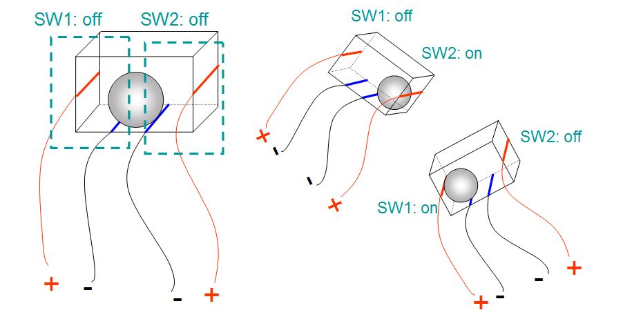
Each tilt switch is made of a plastic box with 4 wires attached and a metal ball inside as illustrated below. As the tilt switch being tilted, the metal ball touches the side wire and close the circuit of one side. Therefore, each tilt switch can be treated as 2 separated switches that indicates tilt in positive or negative direction along 1 axis. Together they have 3 combinations of status.
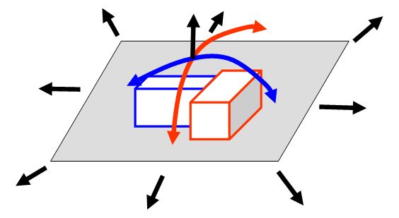
In this project, two tilt switches are attached together perpendicularly to create a 2-axis tilt switch. It can represent 9 different combinations.
- LED Matrix
The LED Matrix used in this project is a 8x8 dual-color LED matrix. For this prototype, I treat this LED matrix as 4*4 single color (only 16 green LEDs at the 4 corners of the matrix are used).
schematics
Notes:
- SW1 and SW2 are associated with tilt switch A; SW3 and SW4 are associated with tilt switch B.
- The pin numbers of the LED matrix are shown in black circles. Column and row numbers are also displayed in the schematics.
- Resistors used in this schematics are chosen to be 1kOhms based on approximation.
Steps taken
Testing hardware
The following sketch is used for hardware testing:
int row[4]={9,10,12,11};
int col[4]={5,6,7,8};
int sw[4]={4,3,2,1};
int val[4]={0,0,0,0};

void setup()
{
  for (int i=0;i<4;i++){
  pinMode(sw[i], INPUT);          //set all switch pins to input
  pinMode(row[i], OUTPUT);     //set all LED pins to output
  pinMode(col[i], OUTPUT);

  digitalWrite(row[i], LOW);       //turn on all LEDs
  digitalWrite(col[i], HIGH);
  }
}

//turn a column on/off based on the status of a corresponding switch
void writeLED(int colNum,int val){
  if (val==HIGH){
    digitalWrite(colNum,LOW);
  }else{
    digitalWrite(colNum,HIGH);
  }
}

void loop()
{
  for (int i=0;i<4;i++){
    val[i] = digitalRead(sw[i]);  // get switch status from input pin
    writeLED(col[i],val[i]);  //turn on/off LEDs
  }
}
In the setup, pin numbers referring to various switches, LED column and rows are stored in arrays for easier access. All the LED row pins are set low and are never changed when this sketch runs. Therefore, changing the value of each column pin can turn on or off a column of 4 LEDs.
In the loop section, the sketch reads 4 integers of 0 or 1 from the 4 switch pins and stores them into an array. It then writes the invert of these value to 4 LED column pins, thus the 4 columns of LEDs reflect the status of 4 switches.
When the tilt switches are tilted, one or two columns of LEDs are lighted.
Programing Techniques
Software description
The final software adds another feature to the original sketch used in hardware testing: replaying past actions when the kit is inactive for some interval of time.
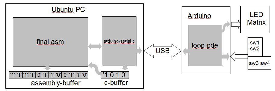
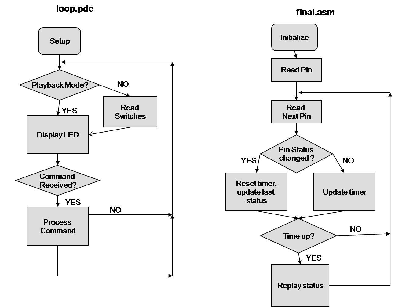
The arduino sketch, loop.pde, still controls the interaction between the switches and the LED matrix, while responding to calls from the PC. The assembly program on the PC constantly reads switch status and stores it into a buffer in memory every tenth of a second or so (depends on the speed of the PC processor and the USB connection). When the assembly program notices the switch status has not changed for a while, it stops arduino from interacting with motion, and sends status data in the PC memory back to the arduino one after another. The arduino receives these data and turns on/off LEDs in the same scheme as it is interacting with motion. After a certain amount of past actions are 'replayed', the arduino restores its user interaction abilities.
Programing Details
- data structure
Arduino-serial.c receives and sends data in ASCII characters, so each pin status is represented by a byte, '0' or '1'. 4 consecutive bytes that represents the status of 4 pins can also be accessed together as double word. For example, '0001' means that PIN 1, 2 and 3 are LOW; PIN 4 is HIGH.
Such characters are stacked into a reserved array in memory, under the label Memory.
- switching between interacting mode and playback mode
To prevent LED from responding to motion when arduino is in the playback mode, I add one more operation "p" to the sketch. This command toggles playback on and off by altering the value of a boolean variable, playback. The code for reading from the 4 input pins is executed only if playback is false.
- impose status to input pins
In order to make arduino replay past actions, I need to overwrite the status of the 4 input pins with imposed values. However, it's a bad idea to switch pins between input/output mode. To work around this, the arduino sketch writes to or reads from the variables that contain the pin status without utilizing any hardware.
- preventing overflow
The reason for choosing to store pin status in memory instead of external files is that I want to simulate the product having a short term memory. Further more, this also leads into an interesting topic about preventing overflow.
Since this program is expected to run continuously as people stops by and play with it, no matter how big the available memory is, it is likely to run out and get a segmentation fault at some point. My approach to this problem is making newer status overwrite the oldest status when maximum size is reached. This creates an interesting effect that the arduino will eventually 'forget' the actions that are replayed for a certain number of times.
To illustrated this effect, I set the maximum size of the part of memory that stores past status to 1024 bytes. Past actions can be played twice or three times before being overwrote by newer ones, if no motion applied after the first playback. Also, the number of bytes being replayed and the time between each playback can also affect how many of times the same action can be replayed.
- text interface
Lastly, I create some useful text output that is readable to common users using ANSI Characters. I find that moving the cursor around makes the program noticeably slower. For instance, I can observe a small lag between the change of LEDs and the updating of status on the screen. (For debugging purposes, I prefer the simple command line output. )
Calibration
- Although the tilt switches only generate binary outputs, they work very accurately and has minimal fluctuation during change of status.
- The LED responds to motion accurately in real time, probably due to the simple visualization scheme used in the sketch.
- The speed at which the status being updated and at playback are partly controlled by calls to a delay() function inside the main loop and inside the playback loop. For a 2G processor, the following function, modified from Lab7, creates a 10ms delay.
;;; ----------------------------------------------------------------
;;; delay 10 ms, or 0.01 sec
;;; ----------------------------------------------------------------
delay:
	pushad
	mov	ecx,10000000
.for	add	eax, 1
	loop	.for
	popad
	ret
Nevertheless, the memory operations and printing to screen slows the program down so that the loop counter decrements less than 10 times per second. If the delay time is further decreased, it's hard for human eyes to keep track of the outputs on the screen. At current setting, some fast vibration may be filtered by the time gap, but the replay performance is satisfactory.
Playback runs faster than the main loop. This is partly due to the fact that playback loop is simpler, and also because that reading from pins has 2 steps: sending the command and waiting for the response, while writing to pins only requires 1 step. I called delay() three times in the playback loop to make the LED display alters at similar pace as they were handled interactively.
Overall, the speed also depends on the speed of the PC processor.
- 3 global constants are defined in the assembly program to specify the number of cycles during each playback, the number of cycles between last action and next playback, and the size of status storage in the memory. For prototyping purposes, I keep them small so that the features of this program can be observed easily.
;;;---------------- Global Constants-----------------------------
%assign replayStepN	50	;# of steps during each playback
%assign alarmMax	100	;# of steps between last action and playback
%assign MAXBUF     1024		;size of buffer in bytes
Programs
Main programs:
//
// loop.pde
// Yang Li
// 12/16/2008
// modified from arduino-loop.pde by D. Thiebaut
//
// This program runs an endless loop on the Arduino, reading input
// from 2 tilt switches and writing output to an LED matrix.
// It also waits for commands of the type
// "p" (toggles playback mode on and off)
// "w d 3 1"(set variable that contains the status of pin 1 to 1)
// "r d" (write value of pin status variable to serial port)
//
// This skech also works without the assembly program.
// It still does the interaction between LED and tilt switches,
// but the interaction will not be stored.
//
//(*features of reading/writing analog pins from the original
//   program are preserved but not used)
//------------------------------------------------------------
// GLOBALS
// -------------------------------------------------------------
//for communication
char buffer[256];
int len;
char *operation;
char *mode;
char *pin;
char *state;

//for Switches and LEDs
int row[4]={9,10,12,11};
int col[4]={5,6,7,8};
int sw[4]={4,3,2,13}; //since pin 1 is used by communication, use pin 13
int val[4]={0,0,0,0};

//switching from sensing mode to play mode
bool playmode=false;
// -------------------------------------------------------------
// PROTOTYPES (function headers)
// -------------------------------------------------------------
void resetAll();
int process();
int writePin( char mode, int pin, int state );
int readPins( char mode );

void changeLED(int colNum, int val);

// -------------------------------------------------------------
// SETUP: initializes port and buffer
// -------------------------------------------------------------
void setup() {
    Serial.begin(9600);
    resetAll();
//LED setup
    for (int i=0;i<4;i++){
    	pinMode(sw[i], INPUT);		//sets switch pins as input
    	pinMode(row[i], OUTPUT);	//sets LED pins as output
    	pinMode(col[i], OUTPUT);

  	digitalWrite(row[i], LOW); 	//turn on all LEDs
  	digitalWrite(col[i], HIGH);
  	}
}

// -------------------------------------------------------------
// RESETALL: clears the buffer and the globals
// -------------------------------------------------------------
void resetAll() {
    buffer[0] = '\0';
    len       = 0;
    operation = mode = pin = state = 0;
}
// -------------------------------------------------------------
// ChangeLED: alter the status of a LED
// -------------------------------------------------------------
void changeLED(int colNum,int val){
  if (val==HIGH){
    digitalWrite(colNum,LOW);
  }else{
    digitalWrite(colNum,HIGH);
  }
}

// -------------------------------------------------------------
// LOOP: main workhorse.  Called repeatedly.  Gets chars from
//       the arduino, and processes it when \n received
// -------------------------------------------------------------
void loop() {
/*----------Native LED control---------------------*/
  	for (int i=0;i<4;i++){
		if (!playmode){
    		val[i] = digitalRead(sw[i]);  // read input value
		}
		changeLED(col[i],val[i]);
  	}


/*----------read next command-----------------------*/
    int c;
    c = Serial.read();

    // nothing received, nothing to do
    if (c==-1) return;

    // \n terminator received, process message
    if ( c=='\n' ) {
        if ( process() ) {
	   Serial.println( "Error" );
	}
        resetAll();
        return;
    }

    // something received, but not \n. add to buffer
    buffer[ len++ ] = c;
    buffer[ len ] = '\0';
}

// -------------------------------------------------------------
// MYSTRTOK: equivalent to C strtok function that doesn't seem
//           supported by arduino.  Given a pointer to a string
//           p, returns a pointer q past p that points to a char
//           that is not a space.  If cannot find one, return
//           NULL.
// -------------------------------------------------------------
char* mystrtok( char* p, int skipNonBlank ) {
    char* q=p;
    if ( skipNonBlank ) {
        for ( ; *q != ' ' && *q != '\0'; q++ );
        if ( *q=='\0' ) return NULL;
    }
    for ( ; *q != '\0' && *q==' '; q++ );
    if ( *q == '\0' ) return NULL;
    if ( *q == ' ' ) return NULL;
    return q;
}

// -------------------------------------------------------------
// PROCESS: if we're here it's because we have received a message
//          from the UBUNTU PC.
// -------------------------------------------------------------
int process() {
    char *p;
    int len = strlen( buffer );
    int intPin;
    int intState;

    //--- get the operation: 'w' or 'r'.  Do some error checking---
    operation = mystrtok( buffer, 0 );
	if (*operation=='p'){
		playmode=!playmode;//toggle playmode
		resetAll();
		return 0; //success
	}

    if ( ( !operation || (*operation!='r' && *operation!='w') )
         || ( ( *operation=='r' && len < 3 ) ||( *operation=='w' && len < 7 ) ) ) {
        resetAll();
        return 1; // error
    }

    //--- get the mode: 'd' or 'a' and do some error checking ---
    mode = mystrtok( operation + 1, 0 );
    if (  !mode || ( *mode!='a' && *mode!='d' ) ) {
        resetAll();
        return 1; // success
    }

    //--- if operation is 'r' read the pins ---
    if ( *operation == 'r' ) {
        readPins( *mode );
        resetAll();
        return 0; // success
    }

    //--- if not, operation is 'w', then get pin # and state ---
    pin = mystrtok( mode + 1, 0 );
    if ( !pin ) {
        resetAll();
        return 1; // error
    }
    intPin = atoi( pin );
    if ( intPin < 1 || intPin > 4 ) { //use pin 1(13) 2 3 4
        resetAll();
        return 1; // error
    }

    //--- get the state of the output pin ---
    state = mystrtok( pin+1, 1 );
    if ( !state ) {
        resetAll();
        return 1; // error
    }
    intState = atoi( state );
    if ( intState < 0 || intState > 1 ) {
        resetAll();
        return 1; // error
    }

    //--- write the state to the pin in question ---
    writePin( *mode, intPin, intState );

    resetAll();
    return 0;
}

// -------------------------------------------------------------
// WRITEPIN: depending on mode, writes the state to the pin
// -------------------------------------------------------------
int writePin( char mode, int  intPin, int intState ) {
    if ( mode=='d' )
	val[intPin-1]=intState; //override pin value depending on command
    if ( mode=='a' )
        analogWrite( intPin, intState );
    //delay( 50 ); // 0.05 sec
    //Serial.println( "OK" );
    return 0;
}

// -------------------------------------------------------------
// READPINS: read the status of all the pins and returns it as
//      a string.
// -------------------------------------------------------------
int readPins( char mode ) {
  int i;
  if ( mode=='d' ) {
        for ( i=0; i<4; i++ ) {
        	Serial.print(val[i]); //get pin state from val not reading
        }
  }
  if ( mode=='a' ) {
        Serial.print( "a " );
        for ( i=0; i<6; i++ ) {
            Serial.print( analogRead( i ) );
            Serial.print( ' ' );
        }
  }
  Serial.println();
  return 0;
}
;;; final.asm
;;; Yang Li
;;; 12/16/2008
;;;
;;; This program constantly reads 4 bytes of ASCII characters
;;; representing the status of 4 arduino pins from c buffer to memory.
;;; If the switch status has not changed for a while,
;;; it send stored status back to the arduino.
;;;
;;; Sample output:
;;;
;;; ****************************************
;;; *       Interactive LED Matrix         *
;;; *    CSC231 Fall 2008 Final Project    *
;;; *             231a-ac Yang Li          *
;;; ****************************************
;;; Current Switch Status:1101
;;; Time before next playback: 51
;;; Playback? OFF
;;;
;;;
;;; To assemble and run:
;;;   nasm -f elf final.asm
;;; gcc -o arduino-serial arduino-serial.c asm_io.o final.o
;;; ./arduino-serial -b 9600 -p /dev/ttyUSB0

;;; ----------------------- EXTERN LABELS -----------------------
extern serialport_writebyte	; int function
extern serialport_write		; int function
extern serialport_read_until	; int function
extern displayBuffer		; int function

extern buf
extern byte

%include "asm_io.inc"
;;;------------------- Macros------------------------------------
%macro printMSG 1		;print C string
	push 	eax
	mov	eax,%1
	call	print_string
	pop	eax
%endmacro


%macro printStatus 1		;move cursor and print status as a C string
	pushad
	mov	eax,[%1]
	mov	[currentStatus+7],eax ;modify string base on buf
	printMSG  currentStatus	      ;print status message
	popad
%endmacro

%macro printTimer 0		;move cursor and print time to next playback
	push	eax		;as a C string
	printMSG indentTimer
	mov	eax,[alarm]
	call	print_int
	pop	eax
%endmacro

;;;---------------- Global Constants-----------------------------
%assign replayStepN	50	;# of steps during each playback
%assign alarmMax	100	;# of steps between last action and playback
%assign MAXBUF     1024		;size of buffer in bytes
        ;; -------------------------
        ;; data segment
        ;; -------------------------
        section .data
;;; arduino commands
msgR	db	"r d", 0	;read pin status
msgRlen	equ	$-msgR
msgP	db	"p", 0		;toogle playback mode
msgPlen	equ	$-msgP
msgW	db	"w d 1 0",0	;write pin status
msgWlen equ	$-msgW
pinNum  db	"1234"		;ascii characters

;;; counters
alarm	dd	100		;alarm for next playback
lastmove dd	0		;address of last status change
actived  dd	0		;if status has changed since program start

;;; screen display
welcomeMSG db 	"****************************************",10
	db	"*       Interactive LED Matrix         *",10
	db	"*    CSC231 Fall 2008 Final Project    *",10
	db	"*             231a-ac Yang Li          *",10
	db 	"****************************************",10
	db 	"Current Switch Status: ",10
	db 	"Time before next playback: ",10
	db	"Playback? OFF",10,0

startP  db	27,"[8;11H",27,"[31m","ON ",10,0 ;"ON" in red text
endP	db	27,"[8;11H",27,"[30m","OFF",10,0 ;"OFF" in black text
sClear  db      27,"[2J"        ; clear the screen
        db      27,"[1;1H",0    ; bring cursor at position 1,1
currentStatus db 27,"[6;23H","XXXX",10,10,10,0 ;template for displaying status
indentTimer db 27,"[7;27H",27,"[K",20,0	;move cursor and clear previous time

	section .bss
memory  resb    MAXBUF          ; storage for past status


        ;; -------------------------
        ;; code area
        ;; -------------------------
        section .text
        global  asm_main
asm_main:
;;; -------------------------
;;; main loop
;;; -------------------------
;;; Pseudocode:
;;;
;;; welcome()
;;; buf=read_buffer()
;;; memory[0]=buf
;;; i=4
;;; While true:
;;; 	buf = read_buffer()
;;; 	memory[i]=buf
;;; 	if i==0:
;;; 		last_status=MaxBuf-4
;;; 	if (last_status==memory[i]):
;;; 		alarm--
;;; 	else :
;;; 		actived=true
;;; 		alarm=alarmMax
;;; 		last_status=i
;;; 	if (alarm==0):
;;; 		replay()
;;; 		alarm=alarmMax
;;; 	if (esi+4>Maxbuf):
;;; 		i=0
;;; 	else:
;;; 		i+=4
;;; 	delay()
;;; ------------------------
	call 	welcome
	call 	read_buffer	;get first set of status
	printStatus	buf
	mov	eax,dword[buf]	;copy status to memory
	mov	[memory],eax

	mov	ecx,-1		;loop inifinite times
	mov	esi,4 		;initialize index pointer
for:
	push	ecx
	call 	read_buffer	;read buffer
	printStatus buf

	mov	eax,dword[buf]  ;copy status to memory
	mov	[memory+esi],eax

	cmp	esi,0		;test if at index 0 (wrapped around)
	jne	cmpPrevious
	cmp	eax,[memory+MAXBUF-4]	;if yes, cmp with largest index
	jne	notSame
	jmp	same

cmpPrevious:			;if no, cmp with previous index
	cmp	eax,[memory+esi-4]
	jne	notSame
same:
	dec	dword[alarm]	;if same, decrement alarm counter
	jmp	testAlarm
notSame:
	mov	dword[actived],1;if not same, status has changed
	mov	[lastmove],esi	;update last active status
	mov	dword[alarm],alarmMax
				;reset alarm
testAlarm:
	printTimer
	cmp	dword[alarm],0	;test if alarm rings
	jne	notRing
	call	replay		;if yes, replay past actions
	mov	dword[alarm],alarmMax ;reset alarm
notRing:
	cmp	esi,MAXBUF-4	;test memory overflow
	jge	overflow
	add	esi,4		;if not,increment 4 bytes
	jmp	finish
overflow:			;if yes,start from 0
	mov	esi,0
finish:
	call	delay
	pop	ecx


        loop   skip		;replacement for "loop for"
        jmp    next
skip:   jmp    for
next:
        ret
;;; --------------------------------------------
;;; replay: replay past status
;;; modified registers:none
;;; --------------------------------------------
;;; Pseudocode:
;;;
;;; def replay():
;;; 	if (!actived):
;;; 		return
;;; 	togglePlayMode()
;;; 	if (last_move<replayStepN*4):
;;; 		i=MaxBuf-replayStepN*4+last_move
;;; 	else:
;;; 		i=last_move-4*replayStepN
;;; 	for k in range(replayStepN):
;;; 		loopSwitches(esiPointer)
;;; 		delay()
;;; 		if (esi+4>MaxBuf):
;;; 			esi=0
;;; 		else:
;;; 			esi+=4
;;; 	togglePlayMode()
;;; --------------------------------------------
replay:
	pushad
  	cmp	dword[actived],0;if never actived,do not replay
 	je	done1

	printMSG startP
	call	togglePlayMode	;tooglePlayMode on

	mov	ecx,replayStepN	;loop N times

				;test enough space to go back N steps
	cmp	dword[lastmove],replayStepN*4
	jl 	.wrap
	mov	esi,[lastmove]	;if yes,go back N steps since last move
	sub	esi,4*replayStepN
	jmp	loopStatus
.wrap:				;if no, wrap around 0
	mov	esi,MAXBUF-replayStepN*4
	add	esi,[lastmove]


	jmp	loopStatus	;prevent short jmps
done1:	jmp	done2		;prevent short jmps

loopStatus:
	push	ecx
	call    writeStatus	;write status to arduino
	pop	ecx

	call	delay		;slow down playback
	call	delay
	call	delay

	cmp	esi,MAXBUF-4	;test array overflow
	jge	.overflow
	add	esi,4		;if not, increment 4 bytes
	jmp	nextStatus
.overflow:
	mov	esi,0		;if yes, start from 0
nextStatus:
	loop	loopStatus	;end outer loop

	call 	togglePlayMode	;play mode off
	printMSG endP
done2:
 	popad
	ret

;;;---------------------------------------------------------------
;;; writeStatus:write arduino command base on status at index esi
;;; modified register edi,eax
;;; --------------------------------------------------------------
writeStatus:
	mov	ecx,4		;loop through 4 status
	mov	edi,0
.for:
	mov	al,[memory+esi+edi]
	mov	[msgW+6],al	;copy status: '0' or '1'
	mov	al,[pinNum+edi]
	mov	[msgW+4],al	;copy switch #
	call	writeMsgW	;send command
	inc	edi
	loop	.for	;end inner loop
	ret


;;;---------------------------------------------------------------
;;; writeMsgW: send write digital command to arduino
;;; --------------------------------------------------------------
writeMsgW:
	pushad
	mov	eax,msgW
	mov	ecx,msgWlen
	call	copyMsg
	call	serialport_write
	popad

	ret

;;;---------------------------------------------------------------
;;; togglePlayMode: change to play mode
;;; --------------------------------------------------------------
togglePlayMode:
	pushad
	mov	eax,msgP
	mov	ecx,msgPlen
	call	copyMsg
	call	serialport_write
	popad

	ret

;;; ---------------------------------------------------------------
;;; read_buffer: read and display buffer
;;; modified registers: eax,ecx
;;; ---------------------------------------------------------------
read_buffer:
	mov	eax, msgR
	mov	ecx, msgRlen	; "r d" read digital pins
	call	copyMsg		; now buf contains "r d"
	call	serialport_write
	call	serialport_read_until
	ret

;;; ----------------------------------------------------------------
;;; delay 10 ms, or 0.01 sec
;;; ----------------------------------------------------------------
delay:
	pushad
	mov	ecx,10000000
.for	add	eax, 1
	loop	.for
	popad
	ret

;;; ----------------------------------------------------------------
;;; copyMsg1: puts array whose address in eax  in external buffer
;;; 	      number of bytes shoudl be in ecx.
;;; ----------------------------------------------------------------
copyMsg:
	pushad
	mov	esi, eax	; source buffer
	mov	edi, buf	; destination buffer in C program
.for	mov	al, [esi]
	mov	[edi], al
	inc	esi
	inc	edi
	loop	.for
	popad
	ret
;;; ----------------------------------------------------------
;;;Welcome
;;;-----------------------------------------------------------
welcome:
	printMSG sClear
	printMSG welcomeMSG
	ret
Other programs needed for compiling:
- arduino-serial.c (Make sure the assembly calls are uncommented)
- asm_io.o
To compile and run:
   nasm -f elf final.asm
   gcc -o arduino-serial arduino-serial.c asm_io.o final.o
   ./arduino-serial -b 9600 -p /dev/ttyUSB0
Sample Output:
****************************************
*       Interactive LED Matrix (v1)    *
*    CSC231 Fall 2008 Final Project    *
*             231a-ac Yang Li          *
****************************************
Current Switch Status:1101
Time before next playback: 51
Playback? OFF
Misc. Information
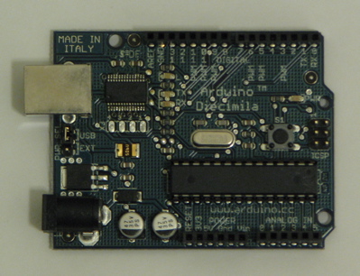
Picture of the Arduino Diecimila chip used in this project:
Project Ideas
- Accessories and Applications
- Rotatable Solar Panel: mount solar panel on an adjustable platform and remote control the tilting angle of the platform to enable maximum sunlight exposure.
- Solar Light: get input from a light meter and decide whether to charge the battery or turn on the light.
- I will discuss with Professor Cardell next week about possible projects on sensors and control for home settings.
- Art and Design
- Visualizing force: read input from a force gauge and visualize the data in some artistic pattern on a series of LEDs or on a LCD display.
- interactive LED box: I will have a low definition screen made of a matrix of LEDs on one side of a box. The LEDs will turn on and off or dimmed to different levels according to the amount of tilt applied to the box measured by an accelerometer inside the box. I also want two sides of the box to sensor force/pressure and reflex it to the LEDs. (Discussed with Professor Cuifo)
Resource
Class Pages
Documentations
- Arduino Official Site
- Arduino Playground wiki documentation center by arduino users
Motors
- Motors overview on different types of motors
- Controlling DC motors basic knowledge on DC motor
- Stepper Motor Basics basic knowledge on stepper motor
- Motor Knob sample code for a stepper motor follows the turns of a potentiometer
Real Projects
Arduino
- Hacking VGA with arduino color visualization on a monitor with arduino.
- Peggy 2.0 Peggy 2.0 is a multiplexed matrix display of 25 by 25 LEDs from Evil Mad Scientist Laboratories. It can be programmed directly from the Arduino environment using a USB-to-TTL cable.
Non-Arduino
- Responsive Environments Group The responsive environments group at the MIT media lab explores how sensor networks augment and mediate human experience, interaction and perception. They have created various projects on developing gadets that collect and use sensor data in innovative ways, such as:
- making a extremely low cost and compact wireless motion sensor that sends out a brief pulse signal when jerked.It can be used for interacting with a crowd of people.[5]
- building a sensate floor made from networked sensor tiles and sending parameters such as footsteps to an external computer via a router.[6]
- TischITP The ITP is a two-year graduate program located in the Tisch School of the Arts whose mission is to explore the imaginative use of communications technologies — how they might augment, improve, and bring delight and art into people’s lives. There projects involves both visual art, and technologies. My favorite one is the CUBIT, which is an interactive surface for multi-touch interactions. People can create amazing visual effects just by pressing fingers on the surface of CUBIT.[7]
