Xilinx ISE Schematics Sequential Circuit
--D. Thiebaut 13:47, 23 April 2012 (EDT)
This lab illustrate how to create a sequential circuit for the Xilinx CoolRunner II CPLD, and how to do behavioral simulation of it.
Introduction
This lab assumes you have gone through the previous lab in this series.
In this lab we will be using flip-flops. Xilinx offers a large library of sequential circuits. Make sure to check it out when searching for circuits: Xilinx Refernce Library.
The Circuit of the Day
The circuit we want to implement in this lab is a sequential circuit controlling 3 LEDs, one Green, on Yellow, and one Red that stay on for one cycle of the clock in the following fashing:
- When the outside command signal called cmd is 1, the cycling goes Green, Yellow, Red, Green, Yellow, etc...
- When the outside command cmd is 0, the cycling stops on Red. If cmd is activated when the light that is on is not Red, the cycling still follows the Green-Yellow-Red path, and stops on Red as long as cmd remains 0.
Generate the equation for this 2-flip-flop circuit and its outputs (R, G, and Y).
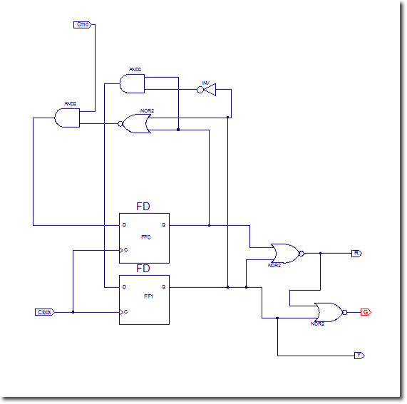
D0 = cmd and not( Q1 ) and not( Q0 )
D1 = not( Q1 ) and Q0
R = not( Q1 or Q0)
Y = Q1
G = not( R + Y )
Illustrated Steps
- Create a new project.
- Create a new source with type schematics.
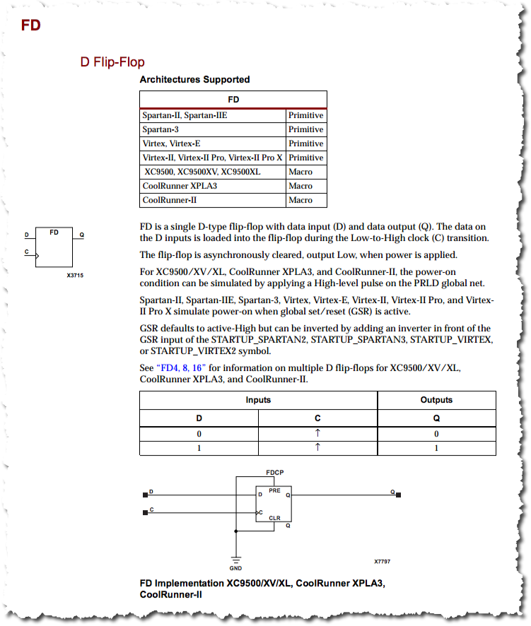
- Xilinx supports many different flip-flop models, some with active low signals, some with negative edge clocks. You can find them all in the Xilinx Library Manual (in pdf form). We'll pick the FD flip-flop for this lab:

- Create your schematics, according to the equations you obtained from your previous analysis.
- Note: You can rotate gates by using Ctrl-R on the keyboard.
- Make sure you add an input marker for the clock signal.
- Tip
- You can verify that a set of wires are connected properly by using cursor mode (you click on the cursor arrow in the vertical menu) and clicking on one of the wires. Every wire connected to that wire, including this wire, will turn red.
- Here's the (not so pretty) circuit we get, given our equations.
