CSC103 Homework 2 2012
--D. Thiebaut 08:58, 9 February 2012 (EST)
This homework is due in class, on 2/15/12. You can work on it in pairs, in which case you should put both names on the work you turn in. If you work in pairs, you must do the work together, i.e. meet one or several time to accomplish all the work with your partner.
Logic Design Problem
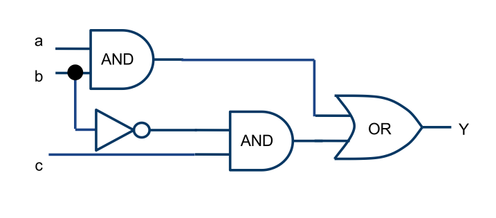
What is the truth table of this circuit? You can figure out the answer in several ways. One is to analyze the circuit "by hand" on a piece of paper and figure out the value of the different signals at the output of the different gates for all possible combinations of the inputs. The other one, longer but fool-proof, is to use the logic simulator we used in class, "wire-up" the circuit, and test its output for all combinations of the inputs.
Word Problem to Schematics
Here is a word problem. Design a circuit with boolean gates that has 3 inputs and 1 output. The inputs are called window1 (or w1 if you prefer a shorter name), window2 (or w2), and rain (or r). The output is called alarm (or a). The circuit should set alarm to 1 whenever the signal r is 1 (it's raining), and either window1 or window2 are 1 (i.e. one of them is open).
Go through the process we went through in class on Wednesday, from the word problem, to the truth table, to the boolean equation of alarm, to the circuit.
Wire up the circuit in the logic simulator. Verify that alarm

