CSC270 Homework 10 2012
--D. Thiebaut 09:30, 20 April 2012 (EDT)
This assignment is due on 4/25, during class. You may work on this assignment in groups of at most two people, and submit one assignment with two names.
Problem #1
We covered the Handshake Protocole in class, where the computer activates a signal called strobe (STB) and the peripheral responds with a signal called acknowledge (ACK).
We wrote a simple program corresponding to the 6811 sending a character to the peripheral (typically an old-style printer).
- Question 1
- Looking at code we wrote, and assuming a very fast printer that absorbs the data bytes as fast as the computer can generate them, what is the maximum speed at which the computer can output bytes to the peripheral? Express the answer in Bytes/sec, Kilobytes/sec, or Megabytes/sec, whatever is appropriate.
One way to speed the transfer up would be to have a sequencer, a finite-state machine, generate the Stobe signal and interact with the peripheral by listening to it ACK signal.
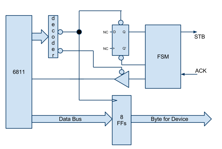
The figure below illustrate how the system would be organized.
Here is the way the system would work:
- The 6811 picks a character to send to the device (printer) and stores it in the 8-bit register shown as "8 FFs" on the figure. An STAA instruction is used, and in its last cycle, the decoder activates a Yi output which does two things: it loads the character on the data-bus in the 8 flipflops, and it activates the preset of the D flipflop, setting its Q output to 1.
- The Q output going to 1 is picked up by the FSM machine which switches state, and now activates the STB signal, indicating to the device that a new byte is available.
- The microprocessor now keeps on executing a LDAA instruction which allows a signal generated by the FSM to be loaded in the MSB of Acca. As long as this bit is 0, it means that the device handshake is not over.
- The FSM keeps STB high until it sees that the device raises ACK. As long as ACK is not high, the FSM stays in the same state.
- As soon as ACK goes high, the FSM switches state and turns STB down.
- The FSM keeps on waiting until the device drops ACK
- As soon as ACK goes back down, the FSM activates the signal to the 6811 to indicate that the transfer is over.
- At the same time it does so, it activates with another signal the CLR (clear) input of the flipflop with the NC clock and data inputs, resetting its Q output to 0.
- Question 2
- Implement the FSM. Show its state diagram. Be careful that the FSM has 2 input signals, so that 4 arrows should leave every state. Figure out the number of states, the number of flipflops required to implement it, and the equations of the D inputs as a function of the Q outputs. What signal should we use for the clock signal?
- Question 3
- How much faster can the 6811 send bytes to the device using this new design?
