CSC231 Homework 7
(c) --DT 13:42, 30 October 2008 (UTC)
Arduino Project Schematics
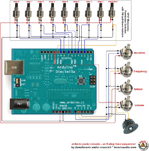
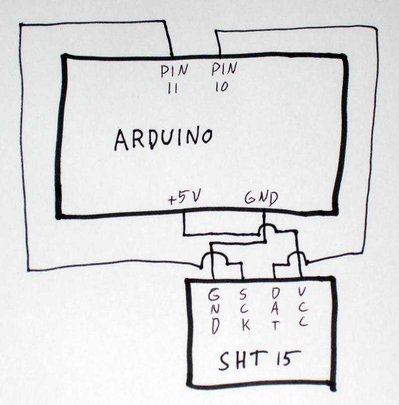
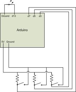
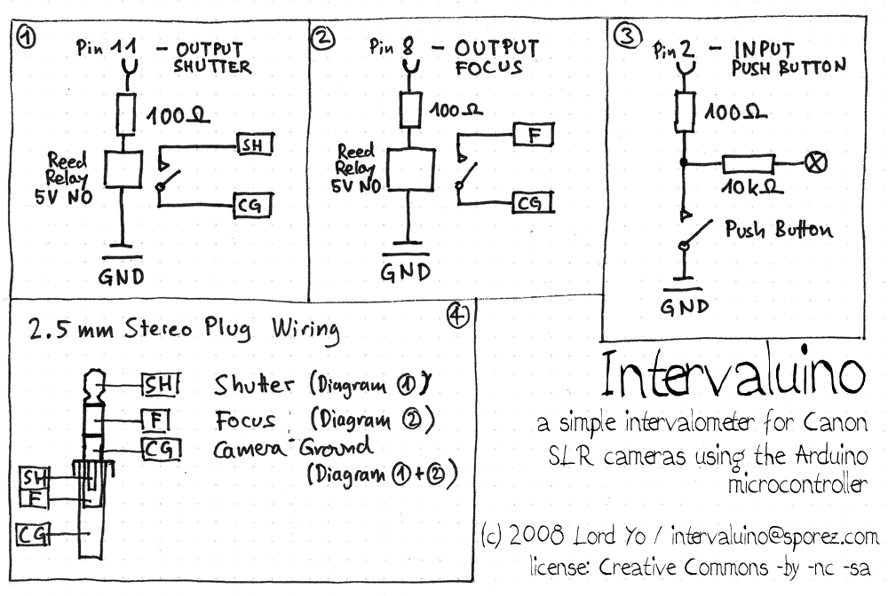
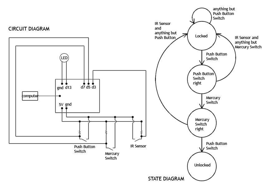
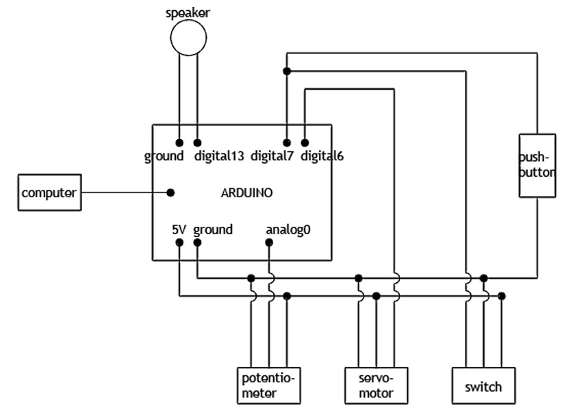
I would like you to generate a diagram showing all the hardware parts you will be using for your project, and how they are connected to each other. This diagram should clearly show the Arduino board as a box with lines going in and out of it, with arrows indicating whether they are inputs or outputs, and the pin numbers. Resistors, switches and so on should be clearly indicated, with their values and part numbers if you have them.
Below are several examples, some fancier than others:
| Diagram | Comments |
|---|---|
|
Very fancy | |
|
Very simple. It doesn't have to be fancy, but I would recommend using MSWord or some drawing package to get something that is computer generated, and a bit more pleasing. The lower block should be labeled so that we have pin numbers, and its name and part number. | |
|
Very fancy | |
|
Very fancy | |
|
Very fancy | |
|
Very fancy |
