ABET-CSC270 Page
This page contains the 3rd week Lab, Homework Assignment, and its Solution
Contents
Lab
Decoder Circuit: the Do-It-Yourself version
Part 1
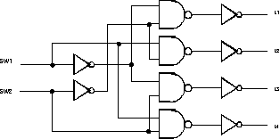
Complete the circuit shown in Figure 1 by adding the name of the circuit inside the logic symbol, and by adding the pin numbers on the inputs and outputs of the gates. Also, do not forget that each circuit requires power and ground.
When you are done, implement the circuit on the breadboard section of your kit. Make sure you have turned off the power before you start wiring. Make sure also that you connect the outputs of the inverters to the four logic indicators. Verify your connections before you turn the power back on. Activate the two inputs and record the outputs in a truth table which you'll include in your report.
Because the inactive outputs are all set to zero, and the active one is set to 1, we refer to this type of circuit as a circuit with "active high" outputs.
Part 2
Now connect L1, L2, L3 and L4 to the input of the inverters rather than their output, and record the variation of L4, L3, L2 and L1 as a function of SW2 and SW1.
SW1 	SW2 	L4 	L3 	L2 	L1
0 	0
0 	1
1 	0
1 	1
You now have the opposite behavior, where the inactive outputs are all 1 except for one that is set to 0. We refer to this type of circuit as a circuit with active-low outputs.
Most decoders work as the last circuit you just tested, rather than the one you first experimented with, although the first circuit had a more "logical" behavior.
The 74LS42 Decoder

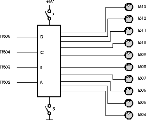
Figure 2: The 7442, as wired on the HeathKit digital trainer.
Block 6 on the circuit board attached to your kit contains a circuit centered on a 7442 (or 74LS42). The logic diagram of the circuit is shown in Figure 2. It has four inputs connected to the test points labeled TP602, TP603, TP604, and TP605. Connect these test points to the data switches. You may want to add a "post-it" note above the data switches to indicate which inputs of the 74LS42 (A, B, C or D) you are activating with the switches. The ten outputs of the 7442 are connected to 10 LEDs, labeled L604 to L613.
To apply power to the 7442, close DIP-switches 7 and 8 in Block 6 (closing a switch means bringing it in the position where the little knob is aligned with the number "1" painted on the switch). (Note: A Dip switch is a "Dual In Line" switch, that is a series of miniature switches that have the same footprint as a regular integrated circuit.)
Turn the Kit power back ON. Activate the data switches and record the variation of the output LEDs in a table
| D | C | B | A | L13 | L12 | L11 | L10 | L9 | L8 | L7 | L6 | L5 | L4 |
Challenge of the Day, #1
Use a 74LS42 to implement a 3-to-8 decoder with enable and active-low outputs.
Challenge of the Day, #2
Use a 74LS42 to implement a majority voter of 3 input signals. You can only use one extra chip, in addition to the 74LS42!
Homework Assignment
This assignment is due on Thursday morning, after Rally Day, at 10:30 a.m. (office, or mailbox).
Exercise 1
Assume that we have a boolean function f(a, b, c, d) = Σ( 5, 7, 15 ).
What is its minimal form, as given by a Karnaugh map?
Assume furthermore we know that the the signals a and b are never both equal to 1 at the same time, and that c and d are never both equal to 00 at the same time. So, for example, the signals a, b, c, d will never be in the state 1 1 0 1, because that would require a, and b to be 1. Similarly, the condition a = 0, b=1, c=0, d=0 will never occur either, because c and d are 0 in this case.
How can we use this information to our advantage, as logic designers?
Exercise 2
What is the simplified expression of the function g(a, b, c, d, e) expressed by the Karnaugh map above?
Exercise 3
Draw the logic diagram for the functions h() and k() below with 4-to-1 multiplexers:
- h( a, b, c, d ) = Σ( 0, 1, 2, 3, 4, 6, 12, 14 )
- k( a, b, c ) = Σ( 0, 1, 2, 3, 7 )
Exercise 4
Draw the logic diagram of the same functions with 8-to-1 multiplexers.
Exercise 5
Same question as for Exercise 3, but this time we know that minterms m5, m7, m12, and m13 correspond to don't care conditions for the function h(), and that minterm m6 is a don't care condition for function k().
Exercise 6
Implement a 16-to-1 multiplexer with only 4-to-1 multiplexers.
Exercise 7
Find the solution to the "Challenge #2 of the day" of Lab 3. You do not have to wire it up (although you are welcome to double check that your circuit works!).
You only have to implement the majority signal.
Explain how you derive your answer, and draw the logic diagram where you will show the 74LS42 as a 3-to-8 decoder with its active-low Enable and its 8 active-low outputs, and its connection to the other gates, all included in one integrated circuit.
Solution
All problems were 1 point each, for a total of 7 points. 1 more point was added to the total, and divided by 2 to get to a number between 1 and 4. The number was then transformed into a letter-grade.
Exercise 1
f = (a’ + c).b.d
the extra conditions give us don’t care conditions, which when applied in the Karnaugh map yield
f = bd
Exercise 2
The vertical column in the left table is a’be’ The horizontal rows in both tables correspond to c’d The square group of 1s in the right table correspond to bc’e
Exercise 3
Apply cd to the control inputs of the 4-to-1 mux.
I0 = 1
I1 = b’
I2 = 0
I3 = b’
the output Y is the function h
Apply ab to the control inputs of the 4-to-1 mux.
I0 = 1
I1 =1
I2 = 0
I3 = c
the output Y is the function k
Exercise 4
Using abc for the control inputs of the 8-to-1 mux (a is the msb), and
I0 = 1
I1 = d
I2 = d’
I3 = 0
I4 = 1
I5 = d
I6 = d’
I7 = 0
the output Y is the function h
Similarly, using an 8-to-1 mux, and using abc as the control inputs (a is the msb), and connecting I0, I1, I2, I3, and I7 to 1, and the others to 0, we have the function k at the output Y.
Exercise 5
The new don't care conditions simplify the circuits some.
The 4-to-1 for h can get 1 on I1 instead of b'.
The 4-to-1 for k gets 1 on I3 instead of c.
The 8-to-1 for h gets 0 on I1, and 1 on I2 and I6.
The 8-to-1 for k does not change.
Exercise 6
It's easier to represent the mux as a function, when drawing is not easy :-)
def mux4to1( I0, I1, I2, I3, c0, c1 )
    dec = c0 + 2*c1
    if dec == 0: return I0
    if dec == 1: return I1
    if dec == 2: return I2
    if dec == 3: return I3
So, if we want the equivalent of a 16-to-1 with only 4-to-1, we can solve it in Python as follows:
def mux16to1( I0, I1, I2, I3, I4, I5, I6, I7, I8, I9, I10, I11, I12, I13, I14, I15, c0, c1, c2, c3 ):

    return mux4to1(
                    mux4to1( I0, I1, I2, I3, c0, c1 ),
                    mux4to1( I4, I5, I6, I7, c0, c1 ),
                    mux4to1( I8, I9, I10, I11, c0, c1 ),
                    mux4to1( I12, I13, I14, I15, c0, c1 ),
                    c2, c3 )
Exercise 7
The challenge of the day: The decoder generates all the minterms of the input. The decoder with active-low outputs generates the inverted minterms, or the Maxterms of the 3 inputs. Since we want to genereate the majority function of a, b, and c, we use the Maxterm form.
Majority( a, b, c ) = Π( 0, 1, 2, 4 ) = M0 . M1 . M2 . M4
So just use 3 AND gates and AND together Y0', Y1', Y2' and Y3' ! ! !

