CSC270 Lab 2 2011
--D. Thiebaut 22:18, 30 January 2011 (EST)
Contents
LAB #2
The Transisor
The transistor is a three-pole semiconductor. The poles are polarized and have well defined functions. They are called the collector, the base, and the emitter.
The transistor you will be using today is the 2N5772, and the manufacturer (fortunately) marked the poles on the package (E, B, and C).
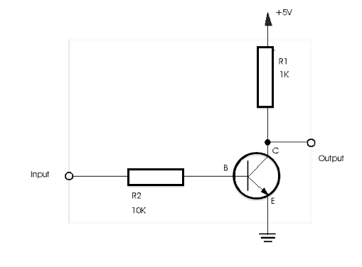
Implement the circuit shown below. Connect the input of the circuit to a switch, and its output to an Indicator. Observe how the output changes as a function of the input. Generate a truth table for this circuit. What logic function does it implement?

Resistor Color Chart
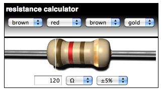
- Use the resistor color chart on your bench to pick the resistors.
- This nifty interactive color-chart can be useful. It is located at http://www.smpspowersupply.com/resistor/resistorcolorcode.html

Experiment #2: Python to the rescue
For this experiment, you will use one of the lab laptops, boot it with Ubuntu (DVD provided), and write a Python program.
The program below, written in Python, generates the truth table of two functions f(a,b,c) and g(a,b,c) of three input variables. f is defined as ((not a) and b ) or c and g is defined as ( not a) and (not b) and (not c).
# truthtable.py
# D. Thiebaut
# how a simple python program can generate the
# truth table of a boolean function
#
# here f is a function of 3 variables
#       _
# f = a.b + c
#     _   _   _
# g = a + b + c

def f( a, b, c ):
    return ( a & (not b) ) | c

def g( a, b, c ):

    return (not a) | (not b) | (not c)

def main():
    print "  a  b  c  |  f  g  "
    print "-----------+--------"
    for a in [ 0, 1 ]:
        for b in [ 0, 1 ]:
            for c in [ 0, 1 ]:
                print "%3d%3d%3d  |%3d%3d" % \
                      ( a, b, c, f( a, b, c ), g( a, b, c ) )

main()
The output is show below:
  a  b  c  |  f  g
-----------+--------
  0  0  0  |  0  1
  0  0  1  |  1  1
  0  1  0  |  0  1
  0  1  1  |  1  1
  1  0  0  |  1  1
  1  0  1  |  1  1
  1  1  0  |  0  1
  1  1  1  |  1  0
- Experiment #1
- Create and run the program above. verify that you get the same truth table as shown here. You may want to mail the code and output to yourself to simplify the taks of writing your report later on. If you are using one of the lab's laptops, you'll find Python 2.6 IDLE under Start, All Programs, Programming Tools.
- Experiment #2
- Modify your program and make it output the truth table for a 2-bit binary adder.
Experiment #3: 2-bit adder
- Implement the 2-bit adder with AND, OR, NOT and possibly XOR gates (the XOR is packaged in a 74LS86 circuit).
- Demonstrate that your circuit works!
Experiment #3: 3-bit adder
- Implement a 3-bit adder with similar gates.
Experiment #4 (depending on time available)
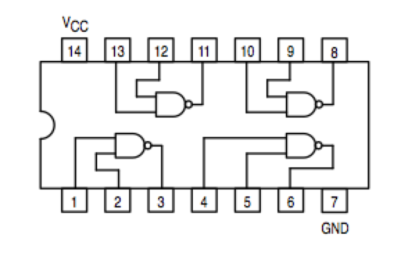
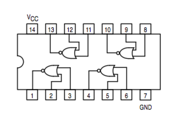
- Implement the 2-bit adder with NAND gates only. The figures below show the schematics of a NAND gate (and of a NOR gate, for completeness).
|
|
Note that the NOR circuit does not have the same pinout as the NAND circuit!!!

