CSC270 Lab 4 2016
--D. Thiebaut (talk) 11:40, 16 February 2016 (EST)
This lab is the transition lab, from combinational logic, to sequential logic. The main instrument to observe sequential circuits is the oscilloscope, which you will be using for the first time today.
|
|
Part 1
NOR RS Latch
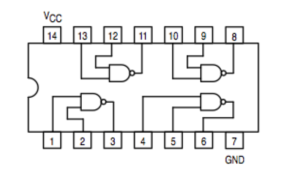
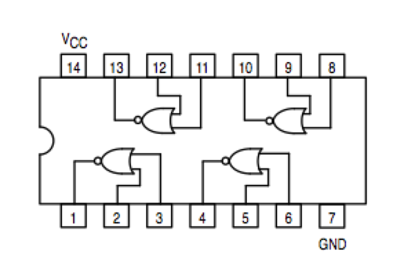
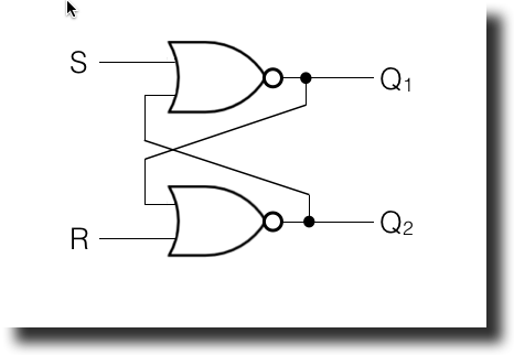
- Build an RS Latch with NOR gates (74LS02), as illustrated in the diagram below. Be careful, the pinout for the NOR gate is not the same as for the NAND gate.
- Connect the R and S signals to the A' and B' Logic Switches (momentary switches), so that they are always 0 when not pressed.
- Push on the R and S switches in a sequence, such as R, R, R, S, S, R, S, and transcribe the behavior of the Latch in a timing diagram.
- Demonstrate the correct behavior of the circuit to your instructor. Show that the circuit "remembers" what switch has being activated last, hence that the latch has "memory."
NAND RS Latch
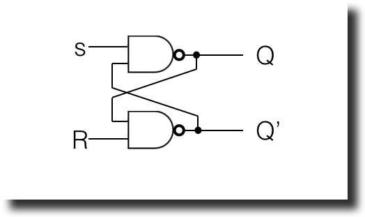
- Build an RS Latch with NAND gates, as illustrated below. Be careful; the pinout for the NOR gate is not the same as for the NAND gate, so you cannot just swap the two circuits!
- Connect the R and S signals to the A and B logic indicators, so that R and S will be 1 when not activated.
- Energize the R and S similarly to the way you did with the NOR latch, and transcribe the behavior in a timing diagram.
- Demonstrate the correct behavior of the circuit to your instructor. Show that the circuit "remembers" what logic switch was last activated.
Part 2
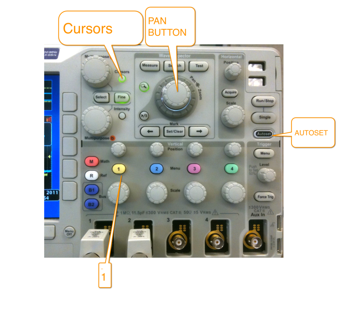
In this section you will work with the oscilloscope and learn how to use its most useful features.
|
Part 3
The digital kit has a clock signal that is oscillating at 1 KHz and 100 KHz. How accurate are these signals. Measure both of these signals and report on the error that might exist between the nominal value and what you measure. Is the error less than 1% of the nominal value? Less than 10% of the nominal value?
Part 4
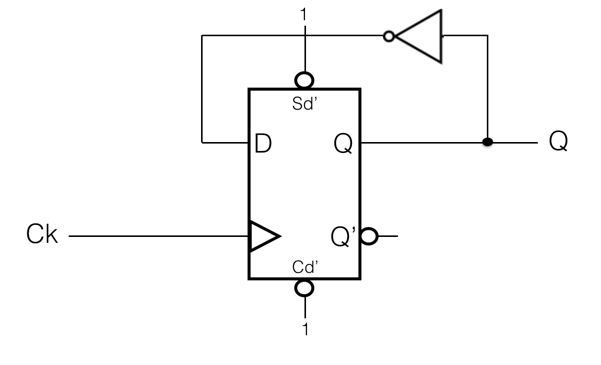
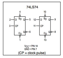
- Implement the following circuit with a 74LS74 D-Flip-flop:
- Connect the Ck signal (the clock) to the Clock signal on the kit, and set the frequency to 1 Hz
- Connect the Ck signal to an Logic Indicator.
- Connect the Q output of the D Flip-flop to another Logic Indicator.
- What is the frequency of the Q signal? 0.5 Hz, 1Hz, or 2 Hz?
- Draw a timing diagram for Ck and Q.
- Slide the frequency switch to 100KHz. Are the Logic Indicators still oscillating ON and OFF?
- Use the scope to observe Ck and Q. Connect Probe 1 to Q, and Probe 2 to Ck.
- Does the timing diagram shown by the scope similar to the timing diagram you created above? Why or why not?
- Make sure you demonstrate the timing diagram on scope to your instructor!
