CSC270 Lab 7 2011
--D. Thiebaut 17:10, 6 March 2011 (EST)
In this lab you will build a 4-state sequencer that activates 3 output LEDs representing the Green, Yellow and Red lights of a traffic light.
GYR Sequencer
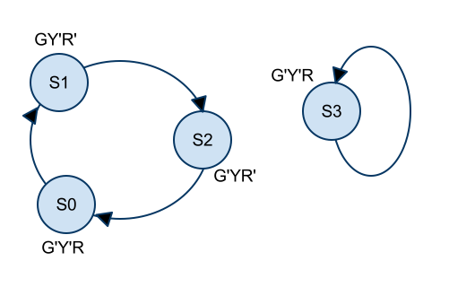
Implement a traffic-light sequencer which activates 3 LEDs, one Green, one Yellow, and one Red, according to the state diagram shown below:

Go through the whole process, addressing each design stage:
- Timing diagram
- State diagram
- State transition table
- Finding the # of D flip-flops
- Assigning flip-flop outputs (Qi) to States.
- State transition table showing the Q outputs at Time n and Time n+1
- Add the outputs to the previous table
- Generate the boolean equations for the D inputs, and for the outputs (G, Y, R). Note, if you find that the G, Y and R signals will require too many different gates, and thus a large number of different circuits on your breadboard area, look into using the 74LS42 decoder instead. Using it would require just 2 chips to generate G, Y, and R! (Think of why this is.)
- Check that your equations are correct by simulating your sequencer with a Python program. You may use the program below for inspiration:
# GYRSequencer.py
# D. Thiebaut
# A very quick and dirty way to check a sequencer...
# This sequencer activates a G, Y, and R light system
# s.t. G is on for 2 cycles, followed by Y for 1 cycle
# followed by R for 1 cycle.  Then the whole cycle repeats

Q1 = 0
Q2 = 0

for step in range( 20 ):

    # the Q1 and Q2 outputs go through combinational logic to generate the new values
    # of D1, D2, and the outputs G, Y, R...
    D1 = Q1 ^ Q2
    D2 = not Q2
    G  = Q1
    Y  = not ( Q1 or Q2 )
    R = not ( G or Y )

    # show the stable circuit signals
    print "Q1Q2 = %d %d  | GYR = %d %d %d" % ( Q1, Q2, G, Y, R )

    # wait for the next clock tick (the user presses Enter)
    raw_input( "> " )

    # as soon as the clock has ticked, D1 and D2 get latched in the flipflops
    # and Q1 and Q2 reflect the values captured.
    Q1 = D1
    Q2 = D2
- Once you have verified that your boolean equations are valid, wire up the circuit, connect the clock inputs to the 1Hz clock signal, and the G, Y, and R signals to LED, and demonstrate that your circuit works.
- Demonstrate that the S3 state works.
- Then take a snapshot of the 3 output signals (G, Y, and R) with the scope when the clock beats at 100KHz.