CSC270 Lab 2 2011
Back to the weekly schedule
LAB #2
© D. Thiebaut, 2009
Experiment #1: Python to the rescue
For this experiment, you need to be working on a computer. Choose which ever platform you like that supports Python.
The program below is written in Python and generates the truth table of two functions f(a,b,c) and g(a,b,c) of three input variables. f is defined as ((not a) and b ) or c and g is defined as ( not a) and (not b) and (not c).
# truthtable.py
# D. Thiebaut
# how a simple python program can generate the
# truth table of a boolean function
#
# here f is a function of 3 variables
#       _
# f = a.b + c
#     _   _   _
# g = a + b + c

def f( a, b, c ):
    return ( a & (not b) ) | c

def g( a, b, c ):

    return (not a) | (not b) | (not c)

def main():
    print "  a  b  c  |  f  g  "
    print "-----------+--------"
    for a in [ 0, 1 ]:
        for b in [ 0, 1 ]:
            for c in [ 0, 1 ]:
                print "%3d%3d%3d  |%3d%3d" % \
                      ( a, b, c, f( a, b, c ), g( a, b, c ) )

main()
The output is show below:
  a  b  c  |  f  g
-----------+--------
  0  0  0  |  0  1
  0  0  1  |  1  1
  0  1  0  |  0  1
  0  1  1  |  1  1
  1  0  0  |  1  1
  1  0  1  |  1  1
  1  1  0  |  0  1
  1  1  1  |  1  0
Go back to your notes from this morning's class, find the boolean expressions we obtained for the majority voter (Majority, Fault, Id0 and Id1), and make the program verify that the equations are correct by making it display the truth table for all four outputs.
Note: if you want to use an xor operator, use the ^-character, as in ( a ^ b ).
Experiment #2
Implement the Id0 and Id1 signals of the majority voter with the simplest circuit you can come up with. Demonstrate that it works and returns the Id of the faulty input, except when the three inputs are the same, in which case the two signals are 1 1.
Experiment #3
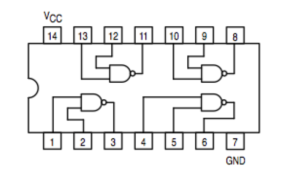
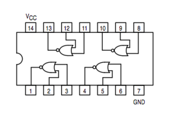
Same as Experiment #2, but use only NAND gates for one of the signals, and only NOR gates for the other.
|
|
Note that the NOR circuit does not have the same pinout as the NAND circuit!!!

