Tutorial: Printed-Circuit Boards
--D. Thiebaut 12:37, 20 June 2011 (EDT)
Contents
Software
All are open-source.
- TinyCAD
- FreePCB
- ViewMate (get the free registration code via email to install)
- PCBExpress/Sunstone: Web site where to order PCB from.
Process
- First create schematics with TinyCAD
- Then route the lines on a 4-layer board with FreePCB
- Check the CAM files generated by FreePCB with ViewMate
- Once the output files are ready, upload them to PCBExpress (accept 4-layers+mask option).
An Example
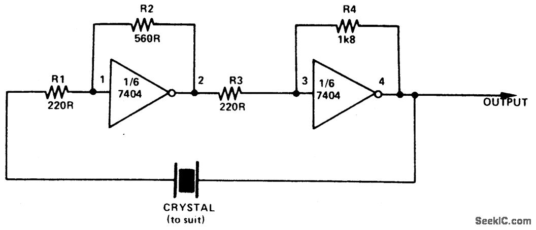
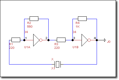
- We'll create a PCB for the following simple circuit taken from seekic.com:
TinyCAD
Generating the Schematics
- Open TinyCAD
- Open the 74TTL library in the left pane
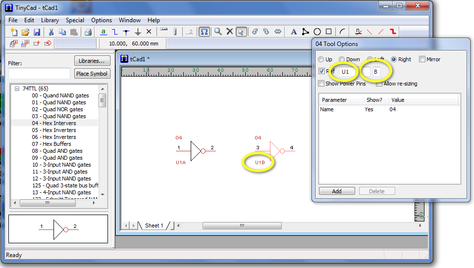
- Pick the Hex Inverters
- Drop two inverters on the blank schematics pane
- Update the reference for each gate (U1A and U1B) in the Tool Options window.
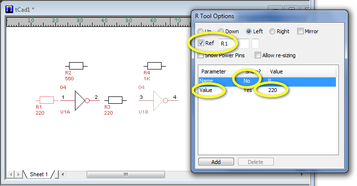
- Open the Analog library, and pick the Resistor, and drop it on the schematics pane where resistors are needed. Use the Tool Options window to set the orientation of the resistors to left.
- For each resistor, use the Tool Option menu to set the Ref to Rn where n is 1, 2, 3, or 4, and Add a value field to the Parameter list for indicating the value in ohm.
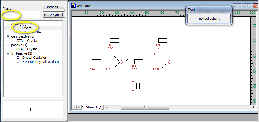
- To add the crystal, search for it in the Filter box and pick the X-Crystal symbol.
- It might be a good time to save your work!
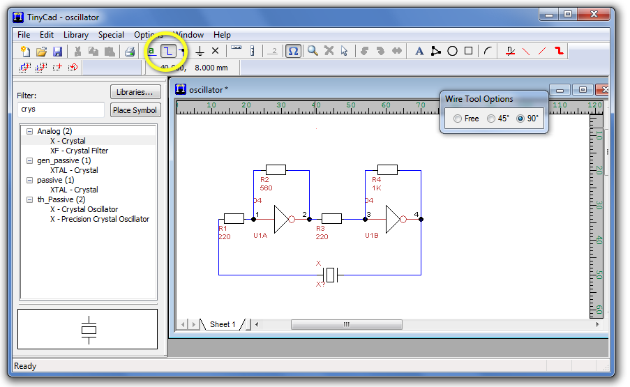
- Click on the Wire tool button and use the mouse to connect all the component pins together, recreating the wiring of the original circuit.
- Add out output connector (J0 - Connection Output)
Assigning Packages to Parts
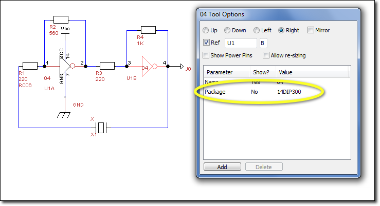
- Depending on the type of circuits you will be using, you can now edit your different parts and add a new Package field, as illustrated here for the 7404 chip.
- Refer to the FreePCB documentation for the type of packages supported. Here's the list of packages picked for this project:
U1   14DIP300
Rn   RC06
X1   CK12-B
J0   HOLE_100_SQR_200
- (where n in Rn is 1, 2, 3, and 4.)
- Assigning packages to the parts now will allow the FreePCB, our next software tool to automatically generate footprints for our parts.
Testing
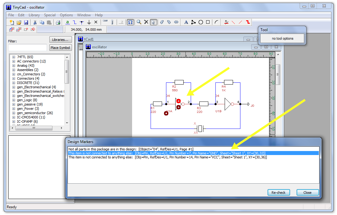
- Check your design by clicking on Special in the top menu, then Check Design Rules.
- Accept the defaults and click Check
- You should get a message indicating that Vcc and GND of the 7404 are not connected.
Generate the Net-List File
- Using the top menu, click Special, Create PCB Net List, and save to file.
- You are now ready for the second step
FreePCB
- The official manual for FreePCB is a Must-Read and can be found here.

